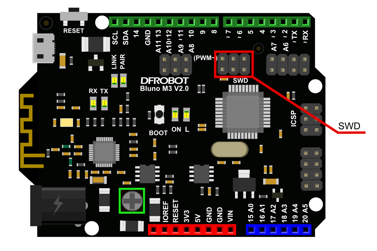
Bluno M3 Interface
In this section, we will introduce some functions about Bluno.
Click here to go back Bluno M3 SKU:DFR0329
GPIO
Overview
There are 39 GPIO pins on Bluno M3 which are compatible with Arduino I/O pins.
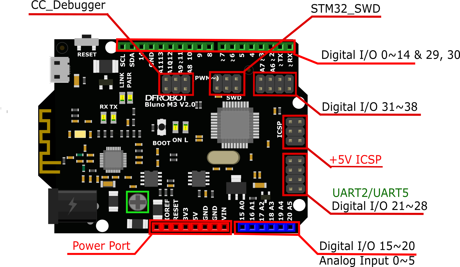
GPIO Reference
Bluno M3's I/O function declarations are identical to Arduino UNO's.
Function Declarations:
pinMode(pin, mode);
digitalRead(pin);
digitalWrite(pin,value); //value=HIGH/LOW
Example
int led = 13;  // Pin 13 has an LED connected on most Arduino boards.

void setup() {
  pinMode(led, OUTPUT);   // initialize the digital pin as an output.
}

void loop() {
  digitalWrite(led, HIGH);   // turn the LED on (HIGH is the voltage level)
  delay(1000);               // wait for a second
  digitalWrite(led, LOW);    // turn the LED off by making the voltage LOW
  delay(1000);               // wait for a second
}
USART
Overview
USART stands for Universal Synchronous/Asynchronous Receiver/Transmitter. Bluno M3 has 5 USARTs in all, and their communication function declarations are also compatible with Arduino UNO:
- Serial1 0(Rx1) & 1(Tx1)
- Serial2 22(Rx2) & 21(Tx2)
- Serial3 30(Rx3) & 29(Tx3)
- Serial4 8(Rx4) & 9(Tx4)
- Serial5 25(Rx5) & 23(Tx5)
USART1 connects to the on-board RX1/TX1 pins. Bluetooth also uses the same USART.
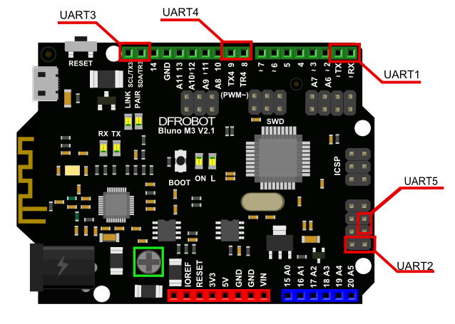
USART Reference
Bluno M3's USART is compatible with Arduino's basic serial communication library. Refer to Arduino's official website for more details.
Example
/**
* 1. Initialize Serial1-Serial5
* 2. Read and write
*
*/
void setup() {
    /* initialize both serial ports.*/
    Serial1.begin(9600);
    Serial2.begin(9600);
    Serial3.begin(9600);
    Serial4.begin(9600);
    Serial5.begin(9600);
    Serial1.println("Bluno M3 Serials test begin .......!");
    Serial1.println("Please choose the Serial to test,and Send a string for it:");

}


void loop() {
    char arr[50];
    int len;
    char ch;
    int i;
    //Serial1.available() judge whether serial1 receive any data
    if (Serial1.available()) {

        Serial1.println("the string you input just now is :");
        //Read Serial1 received data
        ch = Serial1.read()
        //Output data
        Serial1.println(ch);
        Serial1.println("Please choose the Serial to test next,and Send a string for it:");
    }
    if ( Serial2.available()) {
        Serial2.println("the string you input just now is :");
        Serial2.println( ch = Serial2.read());
        Serial2.println("Please choose the Serial to test next,and Send a string for it:");
    }
    if (Serial3.available()) {
        Serial3.println("the string you input just now is :");
        Serial3.println( ch = Serial3.read());
        Serial3.println("Please choose the Serial to test next,and Send a string for it:");}
    if (Serial4.available()) {
        Serial4.println("the string you input just now is :");
        Serial4.println( ch = Serial4.read());
        Serial4.println("Please choose the Serial to test next,and Send a string for it:");  }
    if ( Serial5.available()) {
        Serial5.println("the string you input just now is :");
        Serial5.println( ch = Serial5.read());
        Serial5.println("Please choose the Serial to test next,and Send a string for it:"); }

}
PWM
Overview
The following pins are PWM compatible: 0, 1, 2, 3, 6, 7, 11, 12, 21, 22, 27, 28, 35, 36, 37, 38. Every PWM pin is connected with an internal timer, meaning timer configuration is not necessary.
Bluno M3 supports two PWM modes:
Mode 1:
1.Commandvoid`` ``analogWrite(uint32_t`` ``ulPin,`` ``uint32_t`` ``ulValue): This function will output a 1 KHz square wave. Its duty cycle is decided by "ulValue".
In this mode, the PWM resolution is only 8-bits which will limit PWM output capacity.
Mode 2:
1.Commandvoid`` ``pwmMode(uint32_t`` ``ulPin,`` ``uint32_t`` ``pwmFre,`` ``uint32_t`` ``pwmMode): you can use this function to configure the PWM pin, PWM frequency and mode. There are two types in all: PWM_8_BIT and PWM_12_BIT
InPWM_8_BITMode,pwmFrerange: 4Hz < pwmFre < 281250Hz.
InPWM_12_BITMode,pwmFrerange: 1Hz < pwmFre < 17578Hz.
2.Commandvoid`` ``pwmWrite(uint32_t`` ``ulPin,`` ``uint32_t`` ``ulValue): Outputs a square wave with duty cycle of "ulValue" on Pin "ulPin", the following computational formula:
InMODE_8_BITmode, ulValue range: 0 ~ 255, Dutycycle = ulValue / 255 * 100%
InMODE_12_BITmode, ulValue range: 0 ~ 4095,Dutycycle = ulValue / 4095 * 100%
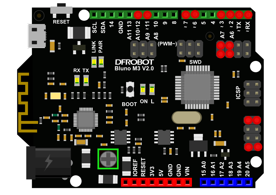
PWM Reference Function
void`` ``analogWrite(uint32_t`` ``ulPin,`` ``uint32_t`` ``ulValue)
Description: Outputs a 1KHz square wave with duty cycle "ulValue" on Pin "ulPin"
Parameter:
- ulPin: PWM pins;
- ulValue: PWM duty cycle value, computational formula: Duty cycle = (ulValue / 255 )* 100%, range: 0~255;
Returns: None;
void`` ``pwmMode(uint32_t`` ``ulPin,`` ``uint32_t`` ``pwmFre,`` ``uint32_t`` ``pwmMode)
Description: configures PWM pin, PWM frequency and PWM mode.
Parameter:
- ulPin: PWM pins;
- pwmFre: PWM frequency, the value range decided by pwmMode;
- pwmMode: PWM resolution: MODE_8_BIT and MODE_12_BIT
Returns: None
Example
Mode 1
  // pwm connected to digital pin 0
  int pwmPin = 0;
  void setup() {
     //nothing happens in setup
 }

  void loop() {

    // fade in from min to max in increments of 5 points:
    for (int fadeValue = 0 ; fadeValue <= 255; fadeValue += 5) {
         // sets the value (range from 0 to 255):
        analogWrite(pwmPin, fadeValue);
         // wait for 30 milliseconds to see the dimming effect
        delay(30);
    }

    // fade out from max to min in increments of 5 points:
    for (int fadeValue = 255 ; fadeValue >= 0; fadeValue -= 5) {
        // sets the value (range from 0 to 255):
        analogWrite(pwmPin, fadeValue);
        // wait for 30 milliseconds to see the dimming effect
        delay(30);
    }
 }
Mode 2
#include <Arduino.h>
 int pwmPin = 0;    // PWM connected to digital pin 0
 int flag = 1;
 void setup() {
     //initailizing the pwmPin,  setting the period of PWM as 2000Hz and it's mode as 8'bit.
     pwmMode(pwmPin, 2000, PWM_8_BIT);
 }

 void loop() {

     // output the duty of the PWM , one is 39% based on the formula privided above.
     pwmWrite(pwmPin, 100);
     while (1);

}
ADC
Overview
An ADC (Analog-to-Digital Converter) is a device that converts a continuous physical quantity (usually voltage) to a digital number that represents the quantity's amplitude.
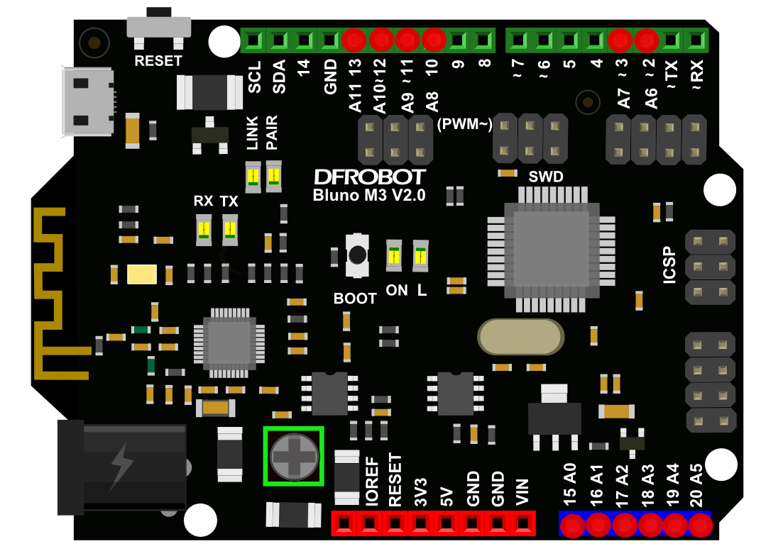
Bluno M3 has 11 ADC pins: A0, A1, A2, A3, A4, A5, A6, A7, A8, A9, A10. Their voltage range is 0~3.3V. They have two working modes:
Mode 1:
1.CommandanalogRead(uint32_t`` ``ulPin): default 10-bit sampling resolution, and its usage is same to Arduino, analogRead()
Mode 2:
1.Commandvoid`` ``adcMode(uint32_t`` ``ulPin,`` ``uint8_t`` ``Mode): Set ADC pin mode:ADC_8_BIT,ADC_10_BIT,ADC_12_BIT.
*ADC_8_BIT. map range: 0~255;
*ADC_10_BIT. map range: 0~1023;
*ADC_12_BIT. map range: 0~4096;
2.Commanduint32_t`` ``adcRead`` ``(uint32_t`` ``ulPin), this function converts the PinulPinanalog input value to the corresponding one in the other mode.
(E.g. If the voltage on A2 is 1.5V, you will get 116 underADC_8_BITpin mode, and you will get 465 and 1861 underADC_10_BITandADC_12_BITpin mode with this commend.)
ADC Reference Function
uint32_t`` ``analogRead(uint32_t`` ``ulPin)
Description: Return Pin ulPin analog value.
Parameter:
- ulPin: ADC pins
Returns: ADC value
void`` ``adcMode(uint32_t`` ``ulPin,`` ``uint8_t`` ``Mode)
Description: Set ADC pin mode
Parameter:
- ulPin: ADC pins
- Mode: Pin mode:
- ADC_8_BIT
- ADC_10_BIT
- ADC_12_BIT
Returns: None
uint32_t`` ``adcRead(uint32_t`` ``ulPin)
Description: Return a mode converted ADC value
Parameter:
- ulPin: Same pin to the adcMode one.
Returns: ADC mode converted result.
Example
Mode 1:
 int sensorPin = 0;    // select the input pin for the potentiometer
 int sensorValue = 0;  // variable to store the value coming from the sensor
 void setup() {

   Serial1.begin(9600);

 }

 void loop() {

   sensorValue = analogRead(sensorPin);
   Serial1.println((int)sensorValue);
   delay(1000);

 }
Mode 2:
 int sensorPin = 0;    // select the input pin for the potentiometer
 int sensorValue = 0;  // variable to store the value coming from the sensor

 void setup() {
    Serial1.begin(9600);
    adcMode(sensorPin, ADC_12_BIT);
 }

 void loop() {

    sensorValue = adcRead(sensorPin);
    Serial1.println((int)sensorValue);
    delay(1000);
}
External Interrupts
Overview
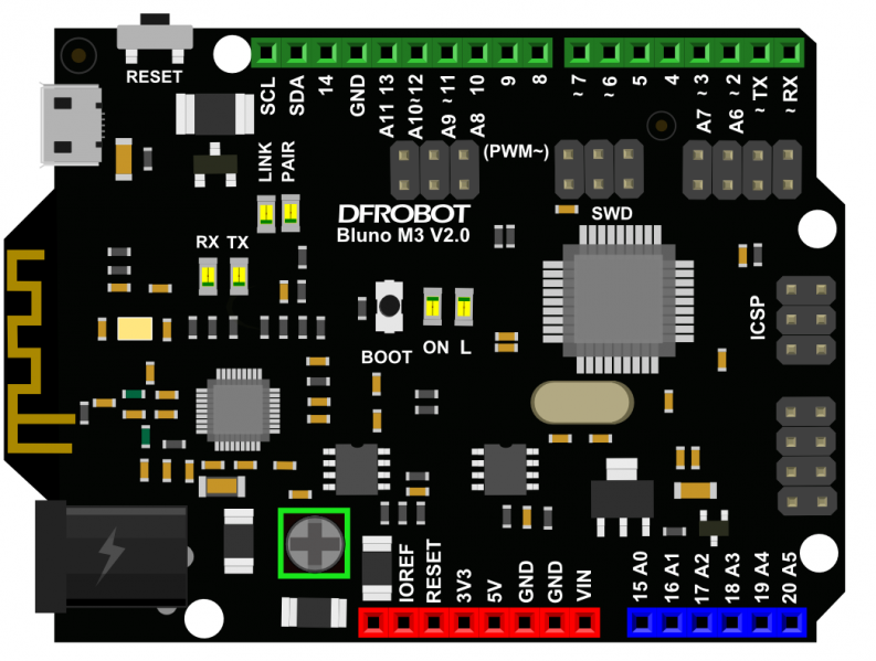
All Bluno M3 digital I/O pins (D0~D38) can be used as external interrupt pins.
Reference Function
void`` ``attachInterrupt(uint32_t`` ``pin,`` ``void`` ``(*callback)(void),`` ``uint32_t`` ``mode)
Description: Configure a specified pin as external interrupt, and register a callback function for the interrupt.
Parameter:
- pin: D0~D38;
- callback: callback function;
- mode: defines when the interrupt should be triggered. Four contstants are predefined as valid values:
- CHANGE to trigger the interrupt whenever the pin changes value
- RISING to trigger when the pin goes from low to high,
- FALLING for when the pin goes from high to low.
Returns: None
Example
//define the extern interrupt pin.
char intNumber = 2;

void setup() {
  //init the Serial1.
  Serial1.begin(9600);
  //register the interrupt handler for the pin and specify the interrupt mode in CHANGE mode
  attachInterrupt(intNumber, warning, CHANGE);
}

void loop() {
}
/*define a function as the handler when the extern Interrupt assert*/
void warning(){
  Serial1.println((int)intNumber);
}
I2C
Overview
I2C protocol (Inter-Integrated Circuit), (refer to I2C wikipedia for more information). Bluno M3 has a I2C interface. The default I2C interface is SDA (30) and SCL(29). It can also be free assigned.
I2C Reference Function
void`` ``begin()
Description: Use default I2C interface: On-board SDA (30) & SCL(29)
Parameter: None
Returns: None
void`` ``begin(uint8_t,`` ``uint8_t)
Description: Define I2C interface, SDA & SCL (D0~D38)
Returns: None
For other usages please refer to Arduino official reference
Example
/*
 *  The sample code implements write/read function on chip 24C256 via I2C bus
 *
 *
 *
 */

#include <Wire.h> //I2C library
#define EEPROM_ADDR 0x50           // I2C Buss address of 24LC256 256K EEPROM
#define PAGESIZE    64             // 64 bytes each Page of 24LC256
int temp ;
void setup()
{
  Wire.begin();   // join I2C bus (address optional for master)
  Serial1.begin(9600);
}

void loop()
{
         int i;
         byte arr[64];
         byte arread[64];
         // TESTS FOR EACH FUNCTION BEGIN HERE
          Serial1.println("the data is going to be write to the 24LC256:");
         for (i = 0; i < PAGESIZE; i++)
         {
             arr[i] = i;
             Serial1.print(i);
             Serial1.print(' ');
             if (i != 0 && i % 10 == 0)
                Serial1.println("");
         }

          Serial1.println("");
         i2c_eeprom_write_page(EEPROM_ADDR, 0, arr, PAGESIZE);
         delay(100);

         i2c_eeprom_read_buffer(EEPROM_ADDR, 0, arread,PAGESIZE);
         Serial1.println("the data is reading from the 24LC256  :");
         delay(1000);

         for (i = 0; i < PAGESIZE; i++)
         {
             Serial1.print(arread[i]);
             Serial1.print(' ');
             if (i != 0 &&i % 10 == 0)
                 Serial1.println("");

         }
          Serial1.println("");
         if (memcmp(arr, arread, PAGESIZE) == 0)
         {
             Serial1.println("the driver of the 24LC256 correct!");
         }
         else
         {
              Serial1.println("the driver of the 24LC256 fault!");
         }

         while (1);
  }

void i2c_eeprom_write_byte( int deviceaddress, unsigned int eeaddress, byte data ) {
    int rdata = data;
    Wire.beginTransmission(deviceaddress);
    Wire.write((int)(eeaddress >> 8)); // MSB
    Wire.write((int)(eeaddress & 0xFF)); // LSB
    Wire.write(rdata);
    Wire.endTransmission();
  }

  // WARNING: address is a page address, 6-bit end will wrap around
  // also, data can be maximum of about 30 bytes, because the Wire library has a buffer of 32 bytes
void i2c_eeprom_write_page( int deviceaddress, unsigned int eeaddresspage, byte* data, byte length ) {
    Wire.beginTransmission(deviceaddress);
    Wire.write((int)(eeaddresspage >> 8)); // MSB
    Wire.write((int)(eeaddresspage & 0xFF)); // LSB
    byte c;
    for ( c = 0; c < length; c++)
      Wire.write(data[c]);
    Wire.endTransmission();
  }

byte i2c_eeprom_read_byte( int deviceaddress, unsigned int eeaddress ) {
    byte rdata = 0xFF;
    Wire.beginTransmission(deviceaddress);
    Wire.write((int)(eeaddress >> 8)); // MSB
    Wire.write((int)(eeaddress & 0xFF)); // LSB
    Wire.endTransmission();
    Wire.requestFrom(deviceaddress,1);
    if (Wire.available()) rdata = Wire.read();
    return rdata;
  }

  // maybe let's not read more than 30 or 32 bytes at a time!
void i2c_eeprom_read_buffer( int deviceaddress, unsigned int eeaddress, byte *buffer, int length ) {
    Wire.beginTransmission(deviceaddress);
    Wire.write((int)(eeaddress >> 8)); // MSB
    Wire.write((int)(eeaddress & 0xFF)); // LSB
    Wire.endTransmission();
    Wire.requestFrom(deviceaddress,length);
    int c = 0;
    for ( c = 0; c < length; c++ )
      if (Wire.available()) buffer[c] = Wire.read();
  }
SPI
Overview
SPI (Serial Peripheral Interface) bus is a synchronous serial communication interface specification used for short distance communication, primarily in embedded systems. Refer to SPI wikipedia for more information.
There are 2 SPI interfaces on Bluno M3: SPI and SPI1.
Reference Functions
Refer to Arduino official functions: SPI Note:
- SPI: SPI.begin();
- SPI1: SPI1.begin()
Example
/**
*Drive SD module via SPI interface
*
*
*
*/


#include "SPI.h"


#define SD_TYPE_ERR     0X00
#define SD_TYPE_MMC     0X01
#define SD_TYPE_V1      0X02
#define SD_TYPE_V2      0X04
#define SD_TYPE_V2HC    0X06

#define CMD0    0
#define CMD1    1
#define CMD8    8
#define CMD9    9
#define CMD10   10
#define CMD12   12
#define CMD16   16
#define CMD17   17
#define CMD18   18
#define CMD23   23
#define CMD24   24
#define CMD25   25
#define CMD41   41
#define CMD55   55
#define CMD58   58
#define CMD59   59
#define MSD_DATA_OK                0x05
#define MSD_DATA_CRC_ERROR         0x0B
#define MSD_DATA_WRITE_ERROR       0x0D
#define MSD_DATA_OTHER_ERROR       0xFF
//SD¿¨»ØÓ¦±ê¼Ç×Ö
#define MSD_RESPONSE_NO_ERROR      0x00
#define MSD_IN_IDLE_STATE          0x01
#define MSD_ERASE_RESET            0x02
#define MSD_ILLEGAL_COMMAND        0x04
#define MSD_COM_CRC_ERROR          0x08
#define MSD_ERASE_SEQUENCE_ERROR   0x10
#define MSD_ADDRESS_ERROR          0x20
#define MSD_PARAMETER_ERROR        0x40
#define MSD_RESPONSE_FAILURE       0xFF


const int slaveSelectPin = 4;
u8  SD_Type=0;

u8 SD_WaitReady(void)
{
  u32 t=0;
  do
  {
    if(SPI.transfer(0xff)==0xff)
    {
      return 0;//is ok!!!
    }
    t++;
  }while(t<0xffffff);
  return 1;
}

void SD_DisSelect(void)
{
    digitalWrite(slaveSelectPin, HIGH);
    SPI.transfer(0xff);
}

u8 SD_Select(void)
{
    digitalWrite(slaveSelectPin, LOW);
    if(SD_WaitReady()==0)
          return 0;
    SD_DisSelect();
    return 1;
}

u8 SD_SendCmd(u8 cmd, u32 arg, u8 crc)
{
    u8 r1;
    u8 Retry=0;
    SD_DisSelect();
    if(SD_Select())
    {
      return 0XFF;
    }
    SPI.transfer(cmd | 0x40);//·Ö±ðдÈëÃüÁî
    SPI.transfer(arg >> 24);
    SPI.transfer(arg >> 16);
    SPI.transfer(arg >> 8);
    SPI.transfer(arg);
    SPI.transfer(crc);
    if(cmd==CMD12)
      SPI.transfer(0xff);
    Retry=0X1F;
    do
    {
    r1=SPI.transfer(0xFF);
    }while((r1&0X80) && Retry--);

    return r1;
}

u8 SD_Initialize(void)
{
    u16 retry;
    u8 r1;
    u8 buf[4];
    u16 i;
    // set the slaveSelectPin as an output:
    pinMode (slaveSelectPin, OUTPUT);
    // initialize SPI:
    SPI.begin();
        SPI.setClockDivider(SPI_CLOCK_DIV256);
        SPI.setDataMode(SPI_MODE3);
    //SPI.setDataMode(SPI_MODE3);
    SPI.setClockDivider(SPI_CLOCK_DIV256);
    for(int i=0;i<10;i++)
    SPI.transfer(0xff);
    retry=20;
    do
    {
        r1=SD_SendCmd(CMD0,0,0x95);
    }while((r1!=0x01)&&retry--);
    SD_Type=0;
    if(r1==0X01)
    {
        if(SD_SendCmd(CMD8,0x1AA,0x87)==1)//SD V2.0
        {
            for(int i=0;i<4;i++)buf[i]=SPI.transfer(0XFF);
            if(buf[2]==0X01&&buf[3]==0XAA)
            {
                retry=0XFFFE;
                do
                {
                    SD_SendCmd(CMD55,0,0X01);
                    r1=SD_SendCmd(CMD41,0x40000000,0X01);
                }while(r1&&retry--);
                if(retry&&SD_SendCmd(CMD58,0,0X01)==0)
                {
                    for(int i=0;i<4;i++)buf[i]=SPI.transfer(0XFF);
                    if(buf[0]&0x40)SD_Type=SD_TYPE_V2HC;
                    else SD_Type=SD_TYPE_V2;
                }
            }
        }else//SD V1.x/ MMC V3
        {
            SD_SendCmd(CMD55,0,0X01);
            r1=SD_SendCmd(CMD41,0,0X01);
            if(r1<=1)
            {
                SD_Type=SD_TYPE_V1;
                retry=0XFFFE;
                do
                {
                    SD_SendCmd(CMD55,0,0X01);
                    r1=SD_SendCmd(CMD41,0,0X01);
                }while(r1&&retry--);
            }else
            {
                SD_Type=SD_TYPE_MMC;//MMC V3
                retry=0XFFFE;
                do
                {
                    r1=SD_SendCmd(CMD1,0,0X01);
                }while(r1&&retry--);
            }
            if(retry==0||SD_SendCmd(CMD16,512,0X01)!=0)SD_Type=SD_TYPE_ERR;
        }
    }
    SD_DisSelect();
    //SPIsetClockDivider(SPI_BaudRatePrescaler_2);
    if(SD_Type)
    return 0;
    else if(r1)return r1;
    return 0xaa;
}

u8 SD_GetResponse(u8 Response)
{
    u16 Count=0xFFF;
    while ((SPI.transfer(0XFF)!=Response)&&Count)Count--;
    if (Count==0)return MSD_RESPONSE_FAILURE;
    else return MSD_RESPONSE_NO_ERROR;
}

u8 SD_RecvData(u8*buf,u16 len)
{
    if(SD_GetResponse(0xFE))return 1;
    while(len--)
    {
        *buf=SPI.transfer(0xFF);
        buf++;
    }

    SPI.transfer(0xFF);
    SPI.transfer(0xFF);
    return 0;
}

u8 SD_GetCSD(u8 *csd_data)
{
    u8 r1;
    r1=SD_SendCmd(CMD9,0,0x01);
    if(r1==0)
    {
      r1=SD_RecvData(csd_data, 16);
    }
  SD_DisSelect();
  if(r1)
    return 1;
  else
    return 0;
}

u32 SD_GetSectorCount(void)
{
    u8 csd[16];
    u32 Capacity;
    u8 n;
    u16 csize;
    if(SD_GetCSD(csd)!=0)
    {
      return 0;
    }

    if((csd[0]&0xC0)==0x40)
    {
        csize = csd[9] + ((u16)csd[8] << 8) + 1;
        Capacity = (u32)csize << 10;
    }
    else
    {
        n = (csd[5] & 15) + ((csd[10] & 128) >> 7) + ((csd[9] & 3) << 1) + 2;
        csize = (csd[8] >> 6) + ((u16)csd[7] << 2) + ((u16)(csd[6] & 3) << 10) + 1;
        Capacity= (u32)csize << (n - 9);
    }
    return Capacity;
}

u8 SD_ReadDisk(u8* buf,u32 sector,u8 cnt)
{
    u8 r1;
    if(SD_Type!=SD_TYPE_V2HC)sector <<= 9;
    if(cnt==1)
    {
        r1=SD_SendCmd(CMD17,sector,0X01);
        if(r1==0)
        {
            r1=SD_RecvData(buf,512);
        }
    }else
    {
        r1=SD_SendCmd(CMD18,sector,0X01);
        do
        {
            r1=SD_RecvData(buf,512);
            buf+=512;
        }while(--cnt && r1==0);
        SD_SendCmd(CMD12,0,0X01);
    }
    SD_DisSelect();
    return r1;//
}

u8 SD_WriteDisk(u8* buf,u32 sector,u8 cnt)
{
    u8 r1;
    if(SD_Type!=SD_TYPE_V2HC)sector *= 512;
    if(cnt==1)
    {
        r1=SD_SendCmd(CMD24,sector,0X01);
        if(r1==0)
        {
            r1=SD_SendBlock(buf,0xFE);
        }
    }
        else
    {
        if(SD_Type!=SD_TYPE_MMC)
        {
            SD_SendCmd(CMD55,0,0X01);
            SD_SendCmd(CMD23,cnt,0X01);
        }
        r1=SD_SendCmd(CMD25,sector,0X01);
        if(r1==0)
        {
            do
            {
                r1=SD_SendBlock(buf,0xFC);
                buf+=512;
            }while(--cnt && r1==0);
            r1=SD_SendBlock(0,0xFD);
        }
    }
    SD_DisSelect();
    return r1;//
}

u8 SD_SendBlock(u8*buf,u8 cmd)
{
    u16 t;
    if(SD_WaitReady())return 1;
    SPI.transfer(cmd);
    if(cmd!=0XFD)
    {
        for(t=0;t<512;t++)
              SPI.transfer(buf[t]);
          SPI.transfer(0xFF);
          SPI.transfer(0xFF);
        t=SPI.transfer(0xFF);
        if((t&0x1F)!=0x05)return 2;
    }
    return 0;
}

void setup()
{
  u32 sector_size;
  u8 ybuf[512]="DFROBOT!";
  u8 xbuf[512];

  Serial1.begin(9600);
 // SPI.begin();
  Serial1.println("Serial1 init is OK!");
   while(SD_Initialize()!=0)
   {
     Serial1.println("SD init Failed");
     delay(1000);
   }
   Serial1.println("SD init OK!");
   sector_size=SD_GetSectorCount()/1024;
  // sector_size=0x3af000;
   Serial1.println(sector_size/4);
   SD_WriteDisk(ybuf,0,1);
   delay(500);
   SD_ReadDisk(xbuf,0,1);

   Serial1.println(xbuf[0]);
   Serial1.println(xbuf[1]);
   Serial1.println(xbuf[2]);
   Serial1.println(xbuf[3]);
   Serial1.println(xbuf[4]);
   Serial1.println(xbuf[5]);
}

void loop() {
  // put your main code here, to run repeatedly:

}
Timer
Overview
Bluno M3 implements a software timer function via a software library. It will meet some user timing requirements on some special occasions. The timer function is encapsulated in the timer class, you only need to define and initialize the object and it will work. The timer supports single and periodic timing interrupt processing modes. In single timing interrupt processing mode, the function only runs once. In periodic mode, it will be executed periodically.
Note: One timer object can be switched between two modes. Timer class also supports the callback function.
Reference function
Timer(void)
Description: Default constructor function
Parameter: None
Returns: None
Timer(uint32_t`` ``ms,`` ``Func`` ``tfunc,`` ``tKind_t`` ``mode,`` ``void`` ``*data)
Description: Support object instantiating and parameter passing
Parameter:
- ms: timing time, unit: ms.
- tfunc: The registered callback function, function mode: void (*Func)(void *);
- mode: Timer mode: t_single or t_period
- t_single: The timer only works for one time, once it finishes the work, the callback function will be destroyed automatically;
- t_period: The timer could be interrupted periodically, and the callback function could be invoked periodically. User could invoke this Timer destructor to destroy this function manually.
- data: The data pointer which callback function should deal with.
Returns: None
~Timer()
Description: Destructor, invoke for destroy the Timer automatically.
Parameter: None
Returns: None
void`` ``config(uint32_t`` ``ms,`` ``Func`` ``tfunc,`` ``tKind_t`` ``mode,`` ``void`` ``*data)
Description: The function which is used to configure the timer object.
Parameter: None
- ms: timing time, unit: ms.
- tfunc: The registered callback function, function mode: void (*Func)(void *);
- mode: Timer mode: t_single or t_period
- data: The data pointer which callback function should deal with.
Returns: None
uint8_t`` ``get_tNum(void)
Description: Return the current Timer serial number.
Parameter: None
Returns: The current Timer serial number (This serial number is assigned when it is created.)
uint32_t`` ``get_resTime(void)
Description: Return the current Timer remaining time.
Parameter: None
Returns: Return the current Timer remaining time.
void`` ``change_callbackFunc(Func`` ``ttFunc)
Description: Change the current Timer callback function.
Parameter:
- ttFunc: Function pointer or the function name.
Returns: None
void`` ``change_mode(tKind_t`` ``mode)
Description: Change the current Timer mode
Parameter:
- mode: t_single or t_period
Returns: None
Example
/***
*
*Bluno M3 Timer Demonstration
*
*/

#include "timerobj.h"
#include <stdlib.h>
unsigned char td;

/*define the objects of the Timer that are best to be a global variable*/
//instantiate a object of the class Timer with the hook function myfunc,and speicify the mode t_period.
Timer timer1(1000, myfunc, t_period, NULL );

Timer timer2(3000, myfunc1, t_period, NULL );


void myfunc(void *data)
{
     Serial1.println("it is processing the first call back function! on timer1\n");
}

void myfunc1(void *data)
{
     static int i;
     i++;
     Serial1.println(i);
     Serial1.println("it is processing the second call back function! on timer2\n");

     if (i == 3)
     {
         Serial1.println("changing the callback function for the timer1\n");
         timer1.change_callbackFunc(myfunc2);  // changing the callback function for the object timer1
      }

}

void myfunc2(void *data)
{

      static int i;
      i++;
      Serial1.println(i);
      Serial1.println("myfunc2");
      if (i == 2)
      {
         Serial1.println("changing the kind of type for timer2\n");
         timer2.change_type(t_single);  // changing the mode for the timer2 from t_period to t_single.
      }
}

void setup() {

      Serial1.begin(9600);

}

void loop() {


}
Flash
Overview
Bluno M3 is microcontroller based on stm32f103 ARM processor. The internal flash is 512k. You could store and run the program on it, or store the user data. There are 256 page in flash, and each page is 2KB. Generally, it requires to erase data first before writing. And it only could write one page at one time. So it is very difficult to make a flash underlying operations on Bluno M3.
So we made a special Flash class for Bluno M3. It divides M3 Flash into two major area: code area and user data area. Code area is place where the program in, it is not visible to the user, and address range is from 0x00000000~0x0807B000. On the other hand, the user data area is available for the client. Read, write or any other operation are allow be allowed in this space. Its address range is from 0x0807B000 ~ 0x08080000. The client could have 20KB storage space even there is no external storage chip. And the data-write function has wiping feature itself. You don't need to consider the flash paging problem anymore, because it also has been integrated in data-write function.
Reference Function
FLASH_Status`` ``ErasePage(uint32_t`` ``Page_Address)
Description: Erase a page.
Parameter:
- Page_Address: Page start address. Computational formula: Page_Address = 0x0807B000 + i * 2048; i = page number,i = (0,1,2,...,19).
Returns: FLASH_Status
- FLASH_BUSY = 1;
- FLASH_ERROR_PG = 2;
- FLASH_ERROR_WRP = 3;
- FLASH_COMPLETE = 4;
- FLASH_TIMEOUT= 5
FLASH_Status`` ``EraseAllPages(void)
Description: Erase all user data area (not including code area)
Parameter:None
Returns: FLASH_Status
- FLASH_BUSY = 1;
- FLASH_ERROR_PG = 2;
- FLASH_ERROR_WRP = 3;
- FLASH_COMPLETE = 4;
- FLASH_TIMEOUT= 5
void`` ``Read`` ``(uint32_t`` ``Addr,`` ``void`` ``*data,`` ``uint32_t`` ``NumByteToWrite)
Description: Read data from assigned address
Parameter:
- Addr: Start address, (0x0807B000~0x08080000);
- data: Data buffer;
- NumByteToWrite: The number of reading byte.
Returns: None
uint16_t`` ``Read(uint32_t`` ``Addr)
Description: Read data (single byte)
Parameter:
- Addr: Data address.
Returns: Return raw byte, (16-bit)
FLASH_Status`` ``Write(uint32_t`` ``WriteAddr,`` ``uint16_t`` ``data)
Description: Write a 16-bit data
Parameter:
- WriteAddr: Flash Address range: 0x0807B000~0x08080000;
- data: The data which will be written
Returns: FLASH_Status
- FLASH_BUSY = 1;
- FLASH_ERROR_PG = 2;
- FLASH_ERROR_WRP = 3;
- FLASH_COMPLETE = 4;
- FLASH_TIMEOUT= 5
void`` ``Write(uint32_t`` ``WriteAddr,`` ``void`` ``*data,`` ``uint32_t`` ``NumByteToWrite)
Description: Write more data to assigned address (Start address)
Parameter:
- WriteAddr: Start writing address, flash range: 0x0807B000~0x08080000
- <data:The> data which will be written;
- NumByteToWrite: The number of the written bytes.
Returns: None
uint32_t`` ``GetFlashSpace(void)
Description: Return the capacity of the user data area
Parameter: None
Returns: Return the capacity of the user data area, unit:byte
Example
#include <Flash.h>

void setup() {
    // initialize the Serial1
    Serial1.begin(9600);
}

void loop() {

    unsigned short temp = 68, readBuf;

    Serial1.println("the data to write is :");
    Serial1.println(temp);
    //write the value 68 to the address 0x08005010 in flash.
    flash.Write(0x08005010, &temp, 1);
    delay(1000);

    Serial1.println("the data from reading is :");
    //read the value to the variable for the address 0x08005010 in flash
    flash.Read(0x08005010, &readBuf, 1);
    Serial1.println(readBuf);

    delay(10000);

}
Servo Application
Overview
We construct a Servo class, to make Bluno M3 have same servo interface with Arduino UNO. If the client need a servo on Bluno M3, he only needs use attach() function.
Example
uint8_t`` ``attach(int`` ``pin)
Description: Drive servo on some pin, and return the pin number.
Parameter:
- pin: Pin number (D0~D38)
Returns: Servo driving pin number
void`` ``write(int`` ``value)
Description: Input servo rotation angle
Parameter:
- value: Servo rotation angle
Returns: None
Example
Library ServoM3 locates Arduino-1.5.5\hardware\arduino\STM32\libraries folder
#include <ServoM3.h>

Servo myservo;  // create servo object to control a servo
                // twelve servo objects can be created on most boards

int pos = 0;    // variable to store the servo position

void setup()
{
  myservo.attach(9);  // attaches the servo on pin 9 to the servo object
}

void loop()
{
  for(pos = 0; pos <= 180; pos += 1) // goes from 0 degrees to 180 degrees
  {                                  // in steps of 1 degree
    myservo.write(pos);              // tell servo to go to position in variable 'pos'
    delay(15);                       // waits 15ms for the servo to reach the position
  }
  for(pos = 180; pos>=0; pos-=1)     // goes from 180 degrees to 0 degrees
  {
    myservo.write(pos);              // tell servo to go to position in variable 'pos'
    delay(15);                       // waits 15ms for the servo to reach the position
  }
}
Ethernet Application
Overview
Bluno M3 is compatible with W5200 Ethernet shield. Here is a sample for how to use it on Bluno M3.
Reference Function
Please refer to Arduino official Ethernet library. Anyway, W5200 shield requires a update version Ethernet library. Please visit our website for library download. DFRobot W5200 wiki
Example
/*
  Web Server (based on the sheld W5200)

 A simple web server that shows the value of the analog input pins.
 using an Arduino Wiznet Ethernet shield.

 Analog inputs attached to pins A0 through A5 (optional)


 */

#include <SPI.h>
#include <Ethernet.h>
//Attention: Official SPI port use "D10" as SS interface.You need to define SS pin acording to the actual SS wire connection
//the default ss pin is attached to 10 pin for the sheld W5200
#define SS    10
#define nRST  8
#define nPWDN 9
#define nINT 3

// Enter a MAC address and IP address for your controller below.
// The IP address will be dependent on your local network:
byte mac[] = {
  0xDE, 0xAD, 0xBE, 0xEF, 0xFE, 0xED };
IPAddress ip(192,168,1,177);

// Initialize the Ethernet server library
// with the IP address and port you want to use
// (port 80 is default for HTTP):
EthernetServer server(80);

void setup() {
  //Next setting parameter is very important!!!! If you don't have reliable reset setting, W5200 maybe will not work!!!!!  //
  pinMode(SS,OUTPUT);
  pinMode(nRST,OUTPUT);
  pinMode(nPWDN,OUTPUT);
  pinMode(nINT,INPUT);
  digitalWrite(nPWDN,LOW);  //enable power

  digitalWrite(nRST,LOW);  //Reset W5200
  delay(10);
  digitalWrite(nRST,HIGH);
 delay(200);       // wait W5200 work
 /////////////////////////////////////////////////////////////
 // Open Serial1 communications and wait for port to open:
  Serial1.begin(9600);
   while (!Serial1) {
    ; // wait for Serial1 port to connect. Needed for Leonardo only
  }


  // start the Ethernet connection and the server:
  Ethernet.begin(mac, ip);
  server.begin();
  Serial1.print("server is at ");
  Serial1.println(Ethernet.localIP());
}


void loop() {
  // listen for incoming clients
  EthernetClient client = server.available();
  if (client) {
    Serial1.println("new client");
    // an http request ends with a blank line
    boolean currentLineIsBlank = true;
    while (client.connected()) {
      if (client.available()) {
        char c = client.read();
        Serial1.write(c);
        // if you've gotten to the end of the line (received a newline
        // character) and the line is blank, the http request has ended,
        // so you can send a reply
        if (c == '\n' && currentLineIsBlank) {
          // send a standard http response header
          client.println("HTTP/1.1 200 OK");
          client.println("Content-Type: text/html");
          client.println("Connnection: close");
          client.println();
          client.println("<!DOCTYPE HTML>");
          client.println("<html>");
                    // add a meta refresh tag, so the browser pulls again every 5 seconds:
          client.println("<meta http-equiv=\"refresh\" content=\"5\">");
          // output the value of each analog input pin
          for (int analogChannel = 0; analogChannel < 6; analogChannel++) {
            int sensorReading = analogRead(analogChannel);
            client.print("analog input ");
            client.print(analogChannel);
            client.print(" is ");
            client.print(sensorReading);
            client.println("<br />");
          }
          client.println("</html>");
          break;
        }
        if (c == '\n') {
          // you're starting a new line
          currentLineIsBlank = true;
        }
        else if (c != '\r') {
          // you've gotten a character on the current line
          currentLineIsBlank = false;
        }
      }
    }
    // give the web browser time to receive the data
    delay(1);
    // close the connection:
    client.stop();
    Serial1.println("client disonnected");
  }
}
SD Application
Overview
An example for Bluno M3 and SD module
Reference Function
Example
/*
  SD card basic file example

 This example shows how to create and destroy an SD card file
 The circuit:
 * SD card attached to SPI bus as follows:
 ** MOSI - pin 11
 ** MISO - pin 12
 ** CLK - pin 13
 ** CS - pin 4

 This example code is in the public domain.

 */
#include <SPI.h>
#include <SD.h>

File myFile;
int cs_pin = 4;       //D4 is attached as cs pin
void setup()
{
  // Open serial communications and wait for port to open:
  Serial1.begin(9600);
  while (!Serial1) {
    ; // wait for serial port to connect. Needed for Leonardo only
  }


  Serial1.print("Initializing SD card...");

  if (!SD.begin(cs_pin)) {
    Serial1.println("initialization failed!");
    return;
  }
  Serial1.println("initialization done.");

  if (SD.exists("example.txt")) {
    Serial1.println("example.txt exists.");
  }
  else {
    Serial1.println("example.txt doesn't exist.");
  }

  // open a new file and immediately close it:
  Serial1.println("Creating example.txt...");
  myFile = SD.open("example.txt", FILE_WRITE);
  myFile.close();

  // Check to see if the file exists:
  if (SD.exists("example.txt")) {
    Serial1.println("example.txt exists.");
  }
  else {
    Serial1.println("example.txt doesn't exist.");
  }

  // delete the file:
  Serial1.println("Removing example.txt...");
  SD.remove("example.txt");

  if (SD.exists("example.txt")) {
    Serial1.println("example.txt exists.");
  }
  else {
    Serial1.println("example.txt doesn't exist.");
  }
}

void loop()
{
  // nothing happens after setup finishes.
}
Generate a Sine-wave by TIM8
Overview
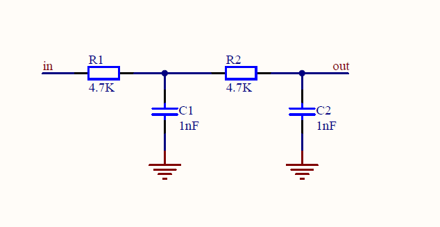
the application is useful for generator a sine-wave by TIM8,the frequence of which can be inditated form 70Hz to 2000Hz. In this application , only the out compare 1 chanel of TIM8
has initialized ,which generate a sine-wave on the PC8.Of course the PC8 must be attached a low pass filter,which can be made samply of two resistances and two capacitances,i.e.
RC integrated circuit.Generally TIM8 have 4 independent channels which can be configure as out compare mode, so user can change the following code to generate mulititude sine-wave at
the same time. the schematic drawing shows as follow:
Example
   #define FAST_MATH_TABLE_SIZE  512
   const float sinTable_f32[FAST_MATH_TABLE_SIZE + 1] = {
   0.00000000f, 0.01227154f, 0.02454123f, 0.03680722f, 0.04906767f, 0.06132074f,
   0.07356456f, 0.08579731f, 0.09801714f, 0.11022221f, 0.12241068f, 0.13458071f,
   0.14673047f, 0.15885814f, 0.17096189f, 0.18303989f, 0.19509032f, 0.20711138f,
   0.21910124f, 0.23105811f, 0.24298018f, 0.25486566f, 0.26671276f, 0.27851969f,
   0.29028468f, 0.30200595f, 0.31368174f, 0.32531029f, 0.33688985f, 0.34841868f,
   0.35989504f, 0.37131719f, 0.38268343f, 0.39399204f, 0.40524131f, 0.41642956f,
   0.42755509f, 0.43861624f, 0.44961133f, 0.46053871f, 0.47139674f, 0.48218377f,
   0.49289819f, 0.50353838f, 0.51410274f, 0.52458968f, 0.53499762f, 0.54532499f,
   0.55557023f, 0.56573181f, 0.57580819f, 0.58579786f, 0.59569930f, 0.60551104f,
   0.61523159f, 0.62485949f, 0.63439328f, 0.64383154f, 0.65317284f, 0.66241578f,
   0.67155895f, 0.68060100f, 0.68954054f, 0.69837625f, 0.70710678f, 0.71573083f,
   0.72424708f, 0.73265427f, 0.74095113f, 0.74913639f, 0.75720885f, 0.76516727f,
   0.77301045f, 0.78073723f, 0.78834643f, 0.79583690f, 0.80320753f, 0.81045720f,
   0.81758481f, 0.82458930f, 0.83146961f, 0.83822471f, 0.84485357f, 0.85135519f,
   0.85772861f, 0.86397286f, 0.87008699f, 0.87607009f, 0.88192126f, 0.88763962f,
   0.89322430f, 0.89867447f, 0.90398929f, 0.90916798f, 0.91420976f, 0.91911385f,
   0.92387953f, 0.92850608f, 0.93299280f, 0.93733901f, 0.94154407f, 0.94560733f,
   0.94952818f, 0.95330604f, 0.95694034f, 0.96043052f, 0.96377607f, 0.96697647f,
   0.97003125f, 0.97293995f, 0.97570213f, 0.97831737f, 0.98078528f, 0.98310549f,
   0.98527764f, 0.98730142f, 0.98917651f, 0.99090264f, 0.99247953f, 0.99390697f,
   0.99518473f, 0.99631261f, 0.99729046f, 0.99811811f, 0.99879546f, 0.99932238f,
   0.99969882f, 0.99992470f, 1.00000000f, 0.99992470f, 0.99969882f, 0.99932238f,
   0.99879546f, 0.99811811f, 0.99729046f, 0.99631261f, 0.99518473f, 0.99390697f,
   0.99247953f, 0.99090264f, 0.98917651f, 0.98730142f, 0.98527764f, 0.98310549f,
   0.98078528f, 0.97831737f, 0.97570213f, 0.97293995f, 0.97003125f, 0.96697647f,
   0.96377607f, 0.96043052f, 0.95694034f, 0.95330604f, 0.94952818f, 0.94560733f,
   0.94154407f, 0.93733901f, 0.93299280f, 0.92850608f, 0.92387953f, 0.91911385f,
   0.91420976f, 0.90916798f, 0.90398929f, 0.89867447f, 0.89322430f, 0.88763962f,
   0.88192126f, 0.87607009f, 0.87008699f, 0.86397286f, 0.85772861f, 0.85135519f,
   0.84485357f, 0.83822471f, 0.83146961f, 0.82458930f, 0.81758481f, 0.81045720f,
   0.80320753f, 0.79583690f, 0.78834643f, 0.78073723f, 0.77301045f, 0.76516727f,
   0.75720885f, 0.74913639f, 0.74095113f, 0.73265427f, 0.72424708f, 0.71573083f,
   0.70710678f, 0.69837625f, 0.68954054f, 0.68060100f, 0.67155895f, 0.66241578f,
   0.65317284f, 0.64383154f, 0.63439328f, 0.62485949f, 0.61523159f, 0.60551104f,
   0.59569930f, 0.58579786f, 0.57580819f, 0.56573181f, 0.55557023f, 0.54532499f,
   0.53499762f, 0.52458968f, 0.51410274f, 0.50353838f, 0.49289819f, 0.48218377f,
   0.47139674f, 0.46053871f, 0.44961133f, 0.43861624f, 0.42755509f, 0.41642956f,
   0.40524131f, 0.39399204f, 0.38268343f, 0.37131719f, 0.35989504f, 0.34841868f,
   0.33688985f, 0.32531029f, 0.31368174f, 0.30200595f, 0.29028468f, 0.27851969f,
   0.26671276f, 0.25486566f, 0.24298018f, 0.23105811f, 0.21910124f, 0.20711138f,
   0.19509032f, 0.18303989f, 0.17096189f, 0.15885814f, 0.14673047f, 0.13458071f,
   0.12241068f, 0.11022221f, 0.09801714f, 0.08579731f, 0.07356456f, 0.06132074f,
   0.04906767f, 0.03680722f, 0.02454123f, 0.01227154f, 0.00000000f, -0.01227154f,
   -0.02454123f, -0.03680722f, -0.04906767f, -0.06132074f, -0.07356456f,
   -0.08579731f, -0.09801714f, -0.11022221f, -0.12241068f, -0.13458071f,
   -0.14673047f, -0.15885814f, -0.17096189f, -0.18303989f, -0.19509032f,
   -0.20711138f, -0.21910124f, -0.23105811f, -0.24298018f, -0.25486566f,
   -0.26671276f, -0.27851969f, -0.29028468f, -0.30200595f, -0.31368174f,
   -0.32531029f, -0.33688985f, -0.34841868f, -0.35989504f, -0.37131719f,
   -0.38268343f, -0.39399204f, -0.40524131f, -0.41642956f, -0.42755509f,
   -0.43861624f, -0.44961133f, -0.46053871f, -0.47139674f, -0.48218377f,
   -0.49289819f, -0.50353838f, -0.51410274f, -0.52458968f, -0.53499762f,
   -0.54532499f, -0.55557023f, -0.56573181f, -0.57580819f, -0.58579786f,
   -0.59569930f, -0.60551104f, -0.61523159f, -0.62485949f, -0.63439328f,
   -0.64383154f, -0.65317284f, -0.66241578f, -0.67155895f, -0.68060100f,
   -0.68954054f, -0.69837625f, -0.70710678f, -0.71573083f, -0.72424708f,
   -0.73265427f, -0.74095113f, -0.74913639f, -0.75720885f, -0.76516727f,
   -0.77301045f, -0.78073723f, -0.78834643f, -0.79583690f, -0.80320753f,
   -0.81045720f, -0.81758481f, -0.82458930f, -0.83146961f, -0.83822471f,
   -0.84485357f, -0.85135519f, -0.85772861f, -0.86397286f, -0.87008699f,
   -0.87607009f, -0.88192126f, -0.88763962f, -0.89322430f, -0.89867447f,
   -0.90398929f, -0.90916798f, -0.91420976f, -0.91911385f, -0.92387953f,
   -0.92850608f, -0.93299280f, -0.93733901f, -0.94154407f, -0.94560733f,
   -0.94952818f, -0.95330604f, -0.95694034f, -0.96043052f, -0.96377607f,
   -0.96697647f, -0.97003125f, -0.97293995f, -0.97570213f, -0.97831737f,
   -0.98078528f, -0.98310549f, -0.98527764f, -0.98730142f, -0.98917651f,
   -0.99090264f, -0.99247953f, -0.99390697f, -0.99518473f, -0.99631261f,
   -0.99729046f, -0.99811811f, -0.99879546f, -0.99932238f, -0.99969882f,
   -0.99992470f, -1.00000000f, -0.99992470f, -0.99969882f, -0.99932238f,
   -0.99879546f, -0.99811811f, -0.99729046f, -0.99631261f, -0.99518473f,
   -0.99390697f, -0.99247953f, -0.99090264f, -0.98917651f, -0.98730142f,
   -0.98527764f, -0.98310549f, -0.98078528f, -0.97831737f, -0.97570213f,
   -0.97293995f, -0.97003125f, -0.96697647f, -0.96377607f, -0.96043052f,
   -0.95694034f, -0.95330604f, -0.94952818f, -0.94560733f, -0.94154407f,
   -0.93733901f, -0.93299280f, -0.92850608f, -0.92387953f, -0.91911385f,
   -0.91420976f, -0.90916798f, -0.90398929f, -0.89867447f, -0.89322430f,
   -0.88763962f, -0.88192126f, -0.87607009f, -0.87008699f, -0.86397286f,
   -0.85772861f, -0.85135519f, -0.84485357f, -0.83822471f, -0.83146961f,
   -0.82458930f, -0.81758481f, -0.81045720f, -0.80320753f, -0.79583690f,
   -0.78834643f, -0.78073723f, -0.77301045f, -0.76516727f, -0.75720885f,
   -0.74913639f, -0.74095113f, -0.73265427f, -0.72424708f, -0.71573083f,
   -0.70710678f, -0.69837625f, -0.68954054f, -0.68060100f, -0.67155895f,
   -0.66241578f, -0.65317284f, -0.64383154f, -0.63439328f, -0.62485949f,
   -0.61523159f, -0.60551104f, -0.59569930f, -0.58579786f, -0.57580819f,
   -0.56573181f, -0.55557023f, -0.54532499f, -0.53499762f, -0.52458968f,
   -0.51410274f, -0.50353838f, -0.49289819f, -0.48218377f, -0.47139674f,
   -0.46053871f, -0.44961133f, -0.43861624f, -0.42755509f, -0.41642956f,
   -0.40524131f, -0.39399204f, -0.38268343f, -0.37131719f, -0.35989504f,
   -0.34841868f, -0.33688985f, -0.32531029f, -0.31368174f, -0.30200595f,
   -0.29028468f, -0.27851969f, -0.26671276f, -0.25486566f, -0.24298018f,
   -0.23105811f, -0.21910124f, -0.20711138f, -0.19509032f, -0.18303989f,
   -0.17096189f, -0.15885814f, -0.14673047f, -0.13458071f, -0.12241068f,
   -0.11022221f, -0.09801714f, -0.08579731f, -0.07356456f, -0.06132074f,
   -0.04906767f, -0.03680722f, -0.02454123f, -0.01227154f, -0.00000000f
};

/*Tim8 ccr address */
#define TIM8_CCR1_Address    0x40013434
#define TIM8_CCR2_Address    0x40013438
#define TIM8_CCR3_Address    0x4001343C
#define TIM8_CCR4_Address    0x40013440
static uint16_t Ctcs_Table[4500];


void RCC_Configuration(void)
{
    /* TIM8 and GPIOC clock enable */
    RCC_APB2PeriphClockCmd(RCC_APB2Periph_TIM8 | RCC_APB2Periph_GPIOC
                           , ENABLE);
    /* DMA 2 clock enable */
    RCC_AHBPeriphClockCmd(RCC_AHBPeriph_DMA2, ENABLE);
}


void GPIO_Configuration(void)
{
    GPIO_InitTypeDef GPIO_InitStructure;

    /* GPIOC Configure: Channel 1 as alternate function push-pull */
    GPIO_InitStructure.GPIO_Pin =  GPIO_Pin_6;
    GPIO_InitStructure.GPIO_Mode = GPIO_Mode_AF_PP;
    GPIO_InitStructure.GPIO_Speed = GPIO_Speed_50MHz;
    GPIO_Init(GPIOC, &GPIO_InitStructure);
}

void DMA_Configuration(void)
{
    DMA_InitTypeDef DMA_InitStructure;

    /* DMA2 Channel3 Config */
    DMA_DeInit(DMA2_Channel3);

    DMA_InitStructure.DMA_PeripheralBaseAddr = (uint32_t)TIM8_CCR1_Address;
    DMA_InitStructure.DMA_MemoryBaseAddr = (uint32_t)Ctcs_Table;
    DMA_InitStructure.DMA_DIR = DMA_DIR_PeripheralDST;
    DMA_InitStructure.DMA_PeripheralInc = DMA_PeripheralInc_Disable;
    DMA_InitStructure.DMA_MemoryInc = DMA_MemoryInc_Enable;
    DMA_InitStructure.DMA_PeripheralDataSize = DMA_PeripheralDataSize_HalfWord;
    DMA_InitStructure.DMA_MemoryDataSize = DMA_MemoryDataSize_HalfWord;
    DMA_InitStructure.DMA_Mode = DMA_Mode_Circular;
    DMA_InitStructure.DMA_Priority = DMA_Priority_High;
    DMA_InitStructure.DMA_M2M = DMA_M2M_Disable;

    DMA_Init(DMA2_Channel3, &DMA_InitStructure);

}
float arm_sin_f32(float x)
{
    float sinVal, fract, in;
    uint16_t index;
    float a, b;
    int32_t n;
    float findex;
    in = x * 0.159154943092f;
    n = (int32_t) in;
    if(x < 0.0f)
    {
      n--;
    }
    in = in - (float) n;
    findex = (float) FAST_MATH_TABLE_SIZE * in;
    index = ((uint16_t)findex) & 0x1ff;
    fract = findex - (float) index;

    a = sinTable_f32[index];
    b = sinTable_f32[index+1];

    sinVal = (1.0f-fract)*a + fract*b;

    return (sinVal);
}
#define SAMPLE_FREQ 282352    // the sample frequence of the pwm that is to be filtered by the attached low pass filter.
void DF_TIM8PwmInit(void)
{
    TIM_TimeBaseInitTypeDef TIM_TimeBaseStructure;
    TIM_OCInitTypeDef TIM_OCInitStructure;
    NVIC_InitTypeDef NVIC_InitStructure;
    DMA_InitTypeDef DMA_InitStructure;

    RCC_Configuration();  //configure the RCC clock of related modules i.e. GPIOC,TIM8 etc.
    GPIO_Configuration();  //configure the GPIO pin for TIM8 as alternate function.
    DMA_Configuration();   //configure DMA channel for TIM8 the indicated out compare channel.
    TIM_TimeBaseStructure.TIM_Period = 255; //set the sine wave

    /*the source lock of TIM8 is 72MHz */
    TIM_TimeBaseStructure.TIM_Prescaler = 1 - 1; // set the prescaler of TIM8 as 0,so the input clock of TIM8 is 72MHz.
    TIM_TimeBaseStructure.TIM_ClockDivision = TIM_CKD_DIV1;
    TIM_TimeBaseStructure.TIM_CounterMode = TIM_CounterMode_Up; // the counter mode is configured as upcounting mode
    TIM_TimeBaseStructure.TIM_RepetitionCounter = 0x0;
    TIM_TimeBaseInit(TIM8,&TIM_TimeBaseStructure);


    /*configure the TIM8 as PWM1 Mode.*/
    TIM_OCInitStructure.TIM_OCMode = TIM_OCMode_PWM1;
    TIM_OCInitStructure.TIM_OutputState = TIM_OutputState_Enable;
    TIM_OCInitStructure.TIM_OutputNState = TIM_OutputNState_Enable;
    TIM_OCInitStructure.TIM_OCPolarity = TIM_OCPolarity_High;
    TIM_OCInitStructure.TIM_OCIdleState = TIM_OCIdleState_Set;
    TIM_OCInitStructure.TIM_OCNIdleState = TIM_OCNIdleState_Reset;
    TIM_OCInitStructure.TIM_Pulse = 0;        // this parameter is very important,since the sine wave generating depends on changing the Pulse value which will be assined to CCRx.
                                              // of course the example is based on the DMA way, with the value of the CCRx register is updated by  TIM8_CCR1_Address,so user can ignore the variable.
    TIM_OC1Init(TIM8, &TIM_OCInitStructure);  // initailize TIM8 out compare chanel
    TIM_DMACmd(TIM8, TIM_DMA_CC1, ENABLE);    // enable the TIM8's out compare 1 chanle addressed by DMA.
}

const float pi = 3.1415;

/*calculate the a table depending on the Freq ,whose elements are used to update TIM8_CCR1_Address's value  */
void DF_SinFreqSet(uint32_t Freq)
{
    float fraction;
    uint16_t i,a;
    uint16_t Sample_Num;

    /*calculate the number of the sample point*/
    Sample_Num = SAMPLE_FREQ / Freq;
    for (i = 0; i < Sample_Num; i++)
    {
      /*use the formula to calculate the value corresponding to each point  */
      Ctcs_Table[i] = 127 * arm_sin_f32( 2 * pi * i / Sample_Num) + 128;

    }

    /*tell the DMA controller the total number of the data is to be transmit */
    DMA2_Channel3->CNDTR = Sample_Num;


}

/*start the sinewave generating.*/
void DF_SinStart(void)
{
    /* DMA enable*/
    DMA_Cmd(DMA2_Channel3, ENABLE);
    /*enable the PWM out compare  of TIM8*/
    TIM_CtrlPWMOutputs(TIM8,ENABLE);
    /*enable the TIM8 module*/
    TIM_Cmd(TIM8,ENABLE);
}

/*stop the sinewave generating*/
void DF_SinStop(void)
{
    /* DMA disable*/
    DMA_Cmd(DMA2_Channel3, DISABLE);
    /*disable the PWM out compare  of TIM8*/
    TIM_CtrlPWMOutputs(TIM8, DISABLE);
     /*disable the TIM8 module*/
    TIM_Cmd(TIM8, DISABLE);
}

void setup()
{
    /*initialize the TIM8 mode and DNMA etc. */
    DF_TIM8PwmInit();
     /*set the sine-wave frequence as 1000Hz*/
    DF_SinFreqSet(1000);
    /*start the sine-wave generating*/
    DF_SinStart();
}

void loop() {

    delay(10000);
    /*expire the sine-wave Generating*/
    DF_SinStop();
    delay(10000);
    /*change the sine-wave frequence as 2KHz*/
    DF_SinFreqSet(2000);
    /*start the sine-wave generating*/
    DF_SinStart();


}
SWD
STM32F103RET6 supports SWD online simulation debugging, it needs 4 pins: GND, RST, SWDIO, SWDCLK. The upload speed can reach 10M/s. Bluno M3 retains SWD port for STM32 standard development. It is easy to monitor STM32 internal register parameters and the status of program running via the SWD port.
If you need this function, you will need an emulator. Compatible emulators are ST-link and J-Link, and their corresponding IDEs are IAR and Keil4. Arduino IDE doesn't support SWD online debugging, so you need to change to IAR. Related instructions are well documented online.
