Introduction
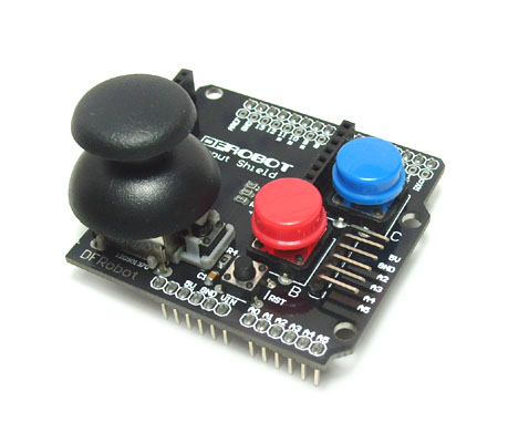
The Arduino Input Shield includes a two axis mini joystick (with moment switch) as well as two colored push buttons. The reserved APC220 Radio Data Module(SKU:TEL0005) interface is to facilitate the realization of wireless rocker button controller. The shield can be easily stacked on top of your Arduino.
Pin Allocation
| Pin | Function |
|---|---|
| Digital 3 | Button B |
| Digital 4 | Button C |
| Digital 5 | Button A |
| Analog 0 | Y axis |
| Analog 1 | X axis |
Sample Code
//This input shield use Digital Pin 3,4,5 (3 buttons) and Analog Pin 0,1 (JS)
// // Upload the code to Arduino
// www.dfrobot.com
// Last modified on 24/12/2009

int x = 1;
int y = 0;
int button_A = 5;
int button_B = 3;
int button_C = 4;
int LED = 13; // Define the LED pin

void setup()
{
pinMode(button_A, INPUT);
pinMode(button_B, INPUT);
pinMode(button_C, INPUT);
pinMode(LED, OUTPUT);
}

void loop()
{
int val_x = analogRead(x);
int val_y = analogRead(y);

if (val_x > 1000 || val_x < 20 || val_y > 1000 || val_y < 20) {
digitalWrite(LED, HIGH);
} else if (digitalRead(button_A) == LOW || digitalRead(button_B) == LOW || digitalRead(button_C) == LOW) {
digitalWrite(LED, HIGH);
} else {
digitalWrite(LED, LOW);
}
}
