Introduction
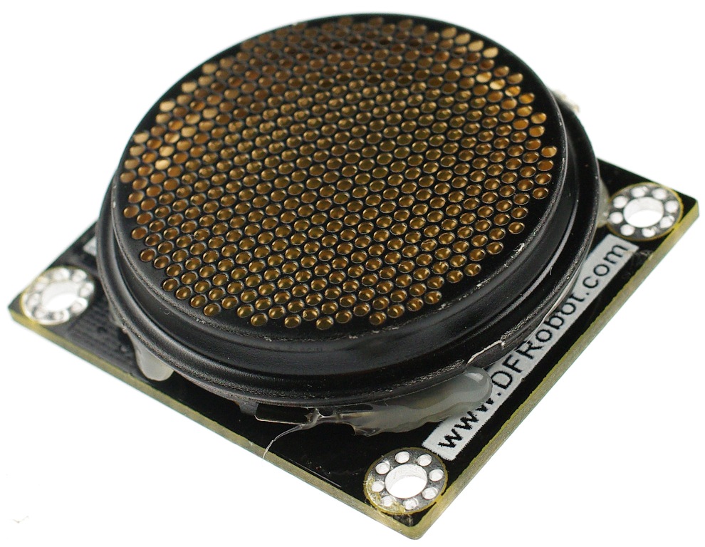
The DFRobot URM05 High Power Ultrasonic Range Finder is based on electrostatic senscomp's 6500 ultrasound transducer design. It can measure a distances of up to 10m. The angle between the ultrasound probes is only 15°, while the majority of the ultrasound is 60°.
Now URM05 has got an upgrade to version 2 and extended some new features. In order to make it easier to connect several range finder modules on your robot, the URM05 v2 support the RS485 interface. we found it's not very convenient to fix the URM05 v1, so we designed four mounting holes for the new version
Applications
Robot navigation and obstacle avoidance measuring distance devices engineering measurement tools industrial control system
Specification
- Power Supply:5v
- Current: normal current 55mA, when sending the instant the current is 2A
- Operating temperature range: 0℃ ~ 40℃
- Interface: TTL level pulse and RS485
- Operating frequency 49.5KHZ. Probe direction angle 15° (-6dB)
- Ultrasonic Distance Measurement: 15 cm to 10.5 m
- Operating modes: single-echo mode and multi-echo mode
- Size: 46x40x21mm(1.8x1.7x0.8")
- Module Weight: About 25g
TTL mode
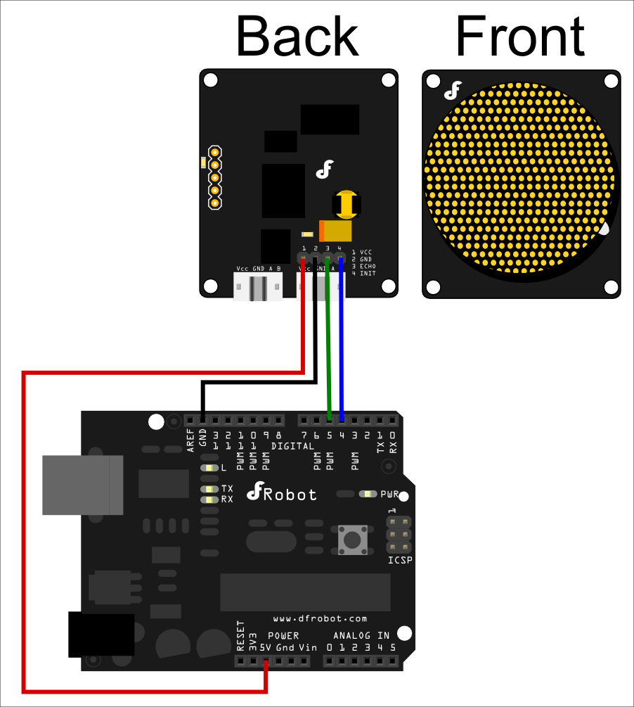
Connection Diagram

Technical Notes

PWM mode information
VDC: 5v power supply @ Max 2A
GND: Connected to Ground
ECHO: PWM signal output pin – 25.4us high level means 2.54cm (1 inch)
INITL: Measurement trigger pin – The low level signal should be longer than 50us in order to trigger the distance measurement
Sample code
/****************** www.DFRobot.com ***********************/
////////////URM05 v2 TTL Module arduino Sample /////////////////////////

#define  INIT   4  // Trigger the measurement
#define  ECHO   5  // Receive the ultrasonic signal feedback
#define  LED    13 // state display

void setup()
{
  Serial.begin(9600);
  pinMode(LED,OUTPUT);//init digital pins
  pinMode(INIT, OUTPUT);
  pinMode(ECHO, INPUT);

  digitalWrite(INIT, HIGH); // turn off the sensor
}

void loop()
{
  digitalWrite(INIT, LOW); // trigger the sensor to measure distance
  delayMicroseconds(10);
  digitalWrite(INIT, HIGH); // finish trigger
  delayMicroseconds(10);

  int distance = pulseIn(ECHO,HIGH);  // Read the signal feedback
  Serial.println(distance);  //Display the distance value in the Serial monitor
  delay(50);

  if (distance >=300)
    digitalWrite(LED,LOW); //100cm > distance >= 30cm Turn on the led
  else
    digitalWrite(LED,HIGH);//10cm < distance < 30cm Turn off the led
}
RS485 Mode
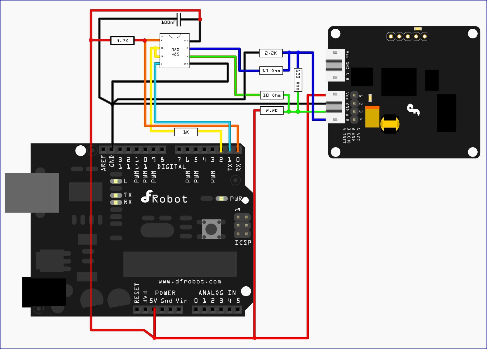
Connection Diagram

NOTE:You may also use IO Expansion Shield For Arduino(V5) (SKU: DFR0088) to simplify the connection.
Technical Notes
-
Baudrate: 19200
-
Data Bits: 8
-
Stop Bits: 1
-
Parity: None
-
Flow Control: None
-
Default Address:Empty
-
Measuring Resolution: 0.1cm
-
LED indication:
- Power supply indication - the one in the center
- Measuring indication - the one on the side
Communication Protocol
Communication Commands and Returns frame Format:
| Header | Address | Length | Cmd | Data | SUM |
|---|---|---|---|---|---|
| 55 | AA | 11 | N | 01 | Data1~DataN |
PS: The sum byte value is the sum of all the byte value before. Just keep one byte from the total sum value.
Setting Address Command:
| Header | Address | Length | Cmd | Data | SUM |
|---|---|---|---|---|---|
| 55 | AA | AB | 01 | 55 | ADDR |
- Default common acceptable address: 0xAB
- Command detail length: 0x01
- Address setting command number: 0x55
- Address number:0x11~0x80
PS: The address of each device can be changed when multiple devices are connected. The new Address must be between 0x11 and 0x80. If the address is set sucessfully, the URM05 will return what it received.If unsucessful, there is no return data.
NOTE: The default address is empty. Please initialize the address before you using it. You could set the address by using Arduino communication or using RS-232 to RS-485 Converter directly with your computer.
Example for setting the module Address to 0x11:
-
Command:
0x55 0xAA 0xAB 0x01 0x55 0x11 0x11 (Set Address to 0x11)Return:
0x55 0xAA 0xAB 0x01 0x55 0x11 0x11 (Address set sucessfully)
Measuring Distance Command:
| Header | Address | Length | Cmd | SUM |
|---|---|---|---|---|
| 55 | AA | Addr | 00 | 02 |
- Command detail length: 0x00
- Address setting command number: 0x02
- No data bytes
PS: This command is used to get the measuring distance from the URM05. It will trigger the measurement first. Then the sensor will transfer the distance value back to the master. The command will return the measured distance value. The value consists of two bytes. The unit of the value is mm. The first content value is the high byte and the second content value is the low byte.
Example for setting the module Address to 0x11:
-
Command:
0x55 0xAA 0x11 0x00 0x02 0x12 (get the measuring distance value from the device\[0x11\])Return:
0x55 0xAA 0x11 0x02 0x02 0x08 0x1A 36 (The distance value is 207.4cm. \[0x08\*256 0x1A=2074\])
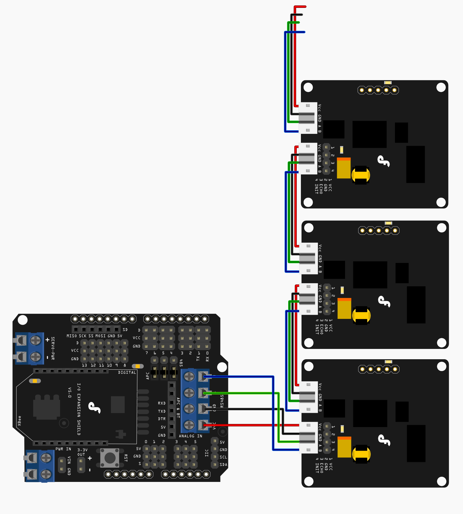
Sensor Networking Diagram

Sample Code
The sketch code:
/*
# The Sample code for driving single URM05 measuring distance function

# Editor : Lauren
# Date   : 2012.8.31
# Ver    : 0.1
# Product: URM05 High Power Ultrasonic Range Finder
# SKU    :

# Specification
* Detecting range: 4cm-700cm
* Resolution     : 0.1cm
* Interface      : RS485
* Units          : Range reported in cm

# Description:

# Drive single URM to measure distance
# You could use IO expansion shield V5 from DFRobot to drive the urm sensor directly with your arduino board.
# The sample code is compatible with the Arduino IDE 1.0 and also the earlier version.

# Considering the sersors with RS485 interface is really hard to use for a beginner, so if any problems, you could e-mail me.
# We'll try to improve the sample code to make it easier to be understood.

# E- Mail Add: [email protected]

*/

#include "Urm5parser.h"

void setup(){
  urmInit();      // Init the URM05 sensor
}

void loop(){
  static unsigned long timePoint = 0;

  runUrm05();      // Drive URM05 Sensor and transmit the protocol to the sensor via RS485 interface
  decodeURM05();   // Read the serial commmands and get the distance value after decode the distance value
  if(millis() - timePoint > 200){
    PrintData();  // print the data
    timePoint = millis();
  }

}

void PrintData(){

  Serial.print("Dis: ");
  Serial.print(urmData / 10.0);
  Serial.print(" cm");
  Serial.println();

}
The library code: please place the library file Urm5parser.h in to the sketch folder.
#if defined(ARDUINO) && ARDUINO >= 100
#include "Arduino.h"
#define printByte(args) Serial.write(args)
#else
#include "WProgram.h"
#define printByte(args) Serial.print(args,BYTE)
#endif

#define SerialPort Serial
#define CommMAXRetry 40
#define TriggerPin 2

#define urmAdd 0x11

// Command list

#define AddComm 0xab
#define DisComm 0x02
#define TempComm 0x03
#define MaxDisComm 0x04

/******************** Variables ****************/

byte readingStep;
byte cmdst[10];
unsigned int urmData;
unsigned long managerTimer = 20;

/******************** Functions ****************/

void initAddr();
void urmInit();
void runUrm05();
void urmTrigger(int id);
void decodeURM05();
void transmitCommands();
void ValidateCmd(byte cmd[]);

/****************** Init sensor ****************/

void urmInit(){

  pinMode(TriggerPin,OUTPUT);  // TTL -> RS485 chip driver pin on Arduino IO expansion shield v5
  digitalWrite(TriggerPin,LOW);// Turn the driver pin to LOW  -> Turn on reading mode for the RS485 interface
                               // Turn the drvier pin to HIGH -> Turn on code transmitting mode for the RS485 interface
  readingStep = 0;
  managerTimer = millis();

  SerialPort.begin(19200);               // Init the RS485 interface
                                         // Also when you are driving the URM04, you could open serial monitor to
                                         // tracing the steps and data feedback from URM04
//  SerialPort.println(" ");
//  SerialPort.println("The default baudrate: 19200");
//  SerialPort.println("Start setting the 485 sensors Address!");
  for(int i = 0 ;i < 10; i  )  cmdst[i] = 0;  //init the URM04 protocol
  cmdst[0]=0x55;
  cmdst[1]=0xaa;

  initAddr();
//  SerialPort.print("Address:");
//  SerialPort.println(urmAdd);
  delay(100);

}

void initAddr(){

  cmdst[2] = AddComm;
  cmdst[3] = 0x01;
  cmdst[4] = 0x55;
  cmdst[5] = urmAdd;
  cmdst[6] = cmdst[0] cmdst[1] cmdst[2] cmdst[3] cmdst[4] cmdst[5];
//  delay(1);
  for(int j = 0; j < 7; j  ){
    printByte(cmdst[j]);
//    delayMicroseconds(50);
  }
  Serial.flush();
//  delay(10);

}

/********************* Drive URM05 and get the data code *************************/

void runUrm05(){                 // You could adjust the sensor measuring rate by changing the managerTimer value

  static unsigned long timer = 0;
  static int num = 0;           // Set the URM05 id to be drived

  if(millis() - timer > managerTimer){
    digitalWrite(TriggerPin, HIGH);  // Turn on transmitting mode for the RS485 interface
    switch(readingStep){

    case 0:
      urmTrigger(urmAdd);
      managerTimer = 0;            // set a interval after trigger the measuring

      break;

    case 1:
      digitalWrite(TriggerPin, LOW); // Turn on reading mode for the RS485 interface
      managerTimer = 300;            // control the flash rate for reading sensor value
      break;

    default:
      readingStep = 0;               // Finish reading the distance and start a new measuring for the sensor
      break;
    }

    if(readingStep < 1)  readingStep  ;  //step manager
    else readingStep = 0;

    timer = millis();
//    digitalWrite(TriggerPin, LOW); //Turn on reading mode for the RS485 interface
  }

}

/********************* Transmit Command via the RS485 interface ***************/

void urmTrigger(int id){  // The function is used to trigger the measuring
  cmdst[2] = id;
  cmdst[3] = 0x00;
  cmdst[4] = DisComm;
  transmitCommands();
  //  SerialPort.println("Trigger!");
}


void transmitCommands(){  // Send protocol via RS485 interface
  cmdst[5]=cmdst[0] cmdst[1] cmdst[2] cmdst[3] cmdst[4];
  delay(1);
  for(int j = 0; j < 6; j  ){
    printByte(cmdst[j]);
//    delayMicroseconds(10);
  }
//  delay(3);
  Serial.flush();
}


/********************* Receive the data and get the distance value from the RS485 interface ***************/

void decodeURM05(){

  if(SerialPort.available()){

    unsigned long timerPoint = millis();

    int RetryCounter = 0;
    byte cmdrd[10];
    for(int i = 0 ;i < 10; i  )  cmdrd[i] = 0;
    int i=0;
//    SerialPort.println("OK");

    boolean flag = true;
    boolean valid = false;
    byte headerNo = 0;

    while(RetryCounter < CommMAXRetry && flag)
    {

      if(SerialPort.available()){
        cmdrd[i]= SerialPort.read();
//        printByte(cmdrd[i]);

        if(i > 7){
          flag=false;
          break;
        }
        if(cmdrd[i] == 0xAA){
          headerNo = i;
          valid = true;
        }
        if(valid && i == headerNo   6){
          flag = false;
          break;
        }
        i   ;
        RetryCounter = 0;
      }
      else{
        RetryCounter  ;
        delayMicroseconds(15);
      }
    }

//    printByte(millis() - timerPoint);

    if(valid)  ValidateCmd(cmdrd);
    else printByte(0xEC);  //Get an invalid error command

  }

}

void ValidateCmd(byte cmd[]){

  byte sumCheck = 0;
  for(int h = 0;h < 7; h   )  sumCheck  = cmd[h];

  if(sumCheck == cmd[7] && cmd[3] == 2 && cmd[4] == 2){

    byte id = cmd[2] - urmAdd;
    urmData = cmd[5] * 256   cmd[6];

//    SerialPort.print(id);
//    SerialPort.print(":");
//    SerialPort.println(urmData);

  }
  else if(cmd[3] == 2 && cmd[4] == 2){
    SerialPort.print("Sum error");
  }

}
