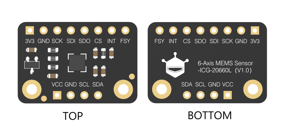
Fermion ICG 20660L 6-Axis Gyro & Accelerometer Motion Sensor Breakout Wiki - DFRobot

ICG 20660L 加速度陀螺仪传感器

Introduction

The ICG-20660L is a high-precision 6-axis IMU module that integrates a 3-axis accelerometer, a 3-axis gyroscope, and on-chip 16-bit ADCs. With up to ±1% initial sensitivity and low noise(6.5mdps/√Hz), it is very suitable for anti-shaking applications. The 6-axis motion sensor includes 512-byte FIFO to reduce traffic on the serial bus interface. Also, it features functions like programmable interrupts, and FSYNC (frame synchronization), which can be used with other image/video capture devices to build up OIS (Optical Image Stabilization)/ EIS (Electric Image Stabilization) projects. Additionally, the small size of the sensor makes it more flexible for various scenarios.

Features

Appliance

Specification

Board Overview

Pin Description

Num Label Description
1 VCC 3.3v~5.5v power input
2 3V3 3.3v power output/input
3 GND GND
4 SCL I2C Clock Line
5 SDA I2C Data Line
6 SCK SPI Clock Control Line
7 SDI SPI Data Line (Input)
8 SDO I2C Address Select Pin/ SPI Data Line (Output)
9 CS SPI chip-select line
10 INT Interrupt Pin
11 FSY Synchronization Digital Input (optional)

*FSY pin function: Advanced users can combine this pin with other sensors (such as image capture modules) to achieve better linkage of the entire project. For specific usage, please refer to datasheet.pdf.

warning_yellow.png

Connections for different communication methods:

I2C连线图EN

SPI连线

Mainboard Default Pin
Micro:bit P9
ESP32 D9
ESP8266 D5
Raspberry Pi BCM27

The interrupt pin is only connected when in use.

Tutorial for M0

Requirements

Wiring Diagram

Please connect your sensor to M0 (or other mainboards) according to the wiring diagram.

M0连线图

/**
 * @brief The constructor of the ICG20660L sensor, using IIC communication.
 * @param addr:  7-bit IIC address, controlled by SDO pin.
 * @n     IIC_ADDR_SDO_H or 0x69:  SDO pull high.(default)
 * @n     IIC_ADDR_SDO_L or 0x68:  SDO pull down.
 * @param pWire:   TwoWire class pointer.
 */
DFRobot_ICG20660L_IIC(uint8_t addr = IIC_ADDR_SDO_H, TwoWire *pWire = &Wire);

/**
 * @brief The constructor of the ICG20660L sensor, using SPI communication.
 * @param csPin:  SPI chip select pin, connected to IO pin of MCU.
 * @param spi: SPIClass class pointer.
 */
DFRobot_ICG20660L_SPI(int csPin, SPIClass *spi);

/**
 * @brief Initialize the sensor, after initialization, all sensors are turned off, and the corresponding configuration
 * @n needs to be turned on through enableSensor.
 * @param mode: Enum variable,from eDataReadMode_t, configure to read sensor data from FIFO or register?
 * @n     eRegMode: Read sensor data from registers.
 * @n     eFIFOMode:Read sensor data from 512 bytes FIFO. Note: Read from FIFO, accelerometer, gyroscope and temperature must all be enabled, 
 * @n and the internal sampling rate must be configured to be consistent. 
 * @return status:
 * @n      0 :   Initialization success.
 * @n      -1:   Interface initialization failed(IIC or SPI).
 * @n      -2:   Failed to read the device ID, the ID is not 0x91
 */
int begin(eDataReadMode_t  mode = eRegMode);

/**
 * @brief Get device ID, ICG20660L is 0x91 (145).
 * @return  If device is ICG20660L, it will return 0x91.
 */
uint8_t readID();

/**
 * @brief Enable sensor, including Accel of xyz axis, Gyro of xyz, temperature. 
 * @param bit: 8-bit byte data. Each bit represents enabling a function bit, as shown in the following table:
 * @n -------------------------------------------------------------------------------------------------------------------
 * @n |       bit7      |     bit6     |      bit5   |    bit4     |     bit3    |     bit2   |    bit1    |    bit0    |
 * @n -------------------------------------------------------------------------------------------------------------------
 * @n |     reserve     |    reserve   | eAccelAxisX | eAccelAxisY | eAccelAxisZ | eGyroAxisX | eGyroAxisY | eGyroAxisZ |
 * @n |                                |            eAccelAxisXYZ                |           eGyroAxisXYZ               |
 * @n |                                |                                eAxisAll                                        |
 * @n -------------------------------------------------------------------------------------------------------------------
 * @n   bit0:  Z-axis of gyro and temperature.
 * @n   bit1:  Y-axis of gyro and temperature.
 * @n   bit2:  X-axis of gyro and temperature.
 * @n   bit3:  Z-axis of acceleration.
 * @n   bit4:  Z-axis of acceleration.
 * @n   bit5:  Z-axis of acceleration.
 * @n   bit6:  reserve.
 * @n   bit7:  reserve.
 * @n Note: Enabling any axis of the gyroscope will automatically enable the on-board temperature sensor.
 * @n   eGyroAxisZ: The bit0 of the bit, enable gyro's z axis and temperature.
 * @n   eGyroAxisY: The bit1 of the bit, enable gyro's y axis and temperature.
 * @n   eGyroAxisX: The bit2 of the bit, enable gyro's X axis and temperature.
 * @n   eAccelAxisZ: The bit3 of the bit, enable accel's z axis.
 * @n   eAccelAxisY: The bit4 of the bit, enable Accel's y axis.
 * @n   eAccelAxisX: The bit5 of the bit, enable Accel's X axis.
 * @n   eGyroAxisXYZ or eGyroAxisX|eGyroAxisY|eGyroAxisZ: The bit0/bit1/bit2 of the bit, enable gyro's xyz axis and temperature.
 * @n   eAccelAxisXYZ or eAccelAxisX|eAccelAxisY|eAccelAxisZ: The bit3/bit4/bit5 of the bit, enable Accel's xyz axis.
 * @n   eAxisAll or eGyroAxisX|eGyroAxisY|eGyroAxisZ|eAccelAxisX|eAccelAxisY|eAccelAxisZ: The bit0/bit1/bit2/bit3/bit4/bit5 of the bit,
 * @n enable temperature, Accel's and gyro's xyz axis. 
 */
void enableSensor(uint8_t bit);

/**
 * @brief Disable sensor, including Accel of xyz axis, Gyro of xyz, temperature. 
 * @param bit: 8-bit byte data. Each bit represents enabling a function bit, as shown in the following table:
 * @n -------------------------------------------------------------------------------------------------------------------
 * @n |       bit7      |     bit6     |      bit5   |    bit4     |     bit3    |     bit2   |    bit1    |    bit0    |
 * @n -------------------------------------------------------------------------------------------------------------------
 * @n |     reserve     |    reserve   | eAccelAxisX | eAccelAxisY | eAccelAxisZ | eGyroAxisX | eGyroAxisY | eGyroAxisZ |
 * @n |                                |            eAccelAxisXYZ                |           eGyroAxisXYZ               |
 * @n |                                |                                eAxisAll                                        |
 * @n -------------------------------------------------------------------------------------------------------------------
 * @n   bit0:  Z-axis of gyro and temperature.
 * @n   bit1:  Y-axis of gyro and temperature.
 * @n   bit2:  X-axis of gyro and temperature.
 * @n   bit3:  Z-axis of acceleration.
 * @n   bit4:  Z-axis of acceleration.
 * @n   bit5:  Z-axis of acceleration.
 * @n   bit6:  reserve.
 * @n   bit7:  reserve.
 * @n Note: Only when the X, Y, and Z axes of the gyroscope are all closed, the temperature sensor will be turned off. 
 * @n Any axis’s turning on will make the temperature sensor not be turned off.
 * @n   eGyroAxisZ: The bit0 of the bit, disable gyro's z axis.
 * @n   eGyroAxisY: The bit1 of the bit, disable gyro's y axis.
 * @n   eGyroAxisX: The bit2 of the bit, disable gyro's X axis.
 * @n   eAccelAxisZ: The bit3 of the bit, disable accel's z axis.
 * @n   eAccelAxisY: The bit4 of the bit, disable Accel's y axis.
 * @n   eAccelAxisX: The bit5 of the bit, disable Accel's X axis.
 * @n   eGyroAxisXYZ or eGyroAxisX|eGyroAxisY|eGyroAxisZ: The bit0/bit1/bit2 of the bit, disable gyro's xyz axis and temperature.
 * @n   eAccelAxisXYZ or eAccelAxisX|eAccelAxisY|eAccelAxisZ: The bit3/bit4/bit5 of the bit, disable Accel's xyz axis.
 * @n   eAxisAll or eGyroAxisX|eGyroAxisY|eGyroAxisZ|eAccelAxisX|eAccelAxisY|eAccelAxisZ: The bit0/bit1/bit2/bit3/bit4/bit5 of the bit, 
 * @n disable temperature, Accel's and gyro's xyz axis. 
 */
void disableSensor(uint8_t bit);

/**
 * @brief Config of gyro's full scale, dlpf bandwidth and internal sample rate. 
 * @param scale  The full scale of gyro, unit: dps(Degrees per second).
 * @n     eFSR_G_125DPS:  The full scale range is ±125 dps.
 * @n     eFSR_G_250DPS:  The full scale range is ±250 dps.
 * @n     eFSR_G_500DPS:  The full scale range is ±500 dps.
 * @param bd  Set 3-db bandwidth.
 * @n     eGyro_DLPF_8173_32KHZ: When the signal is equal to or greater than 8173Hz, there will be obvious attenuation, 3-db attenuation, and the internal sampling rate is 32KHz.
 * @n     eGyro_DLPF_3281_32KHZ: When the signal is equal to or greater than 3281Hz, there will be obvious attenuation, 3-db attenuation, and the internal sampling rate is 32KHz.
 * @n     eGyro_DLPF_250_8KHZ:   When the signal is equal to or greater than 250Hz, there will be obvious attenuation, 3-db attenuation, and the internal sampling rate is 8KHz.
 * @n     eGyro_DLPF_176_1KHZ:   When the signal is equal to or greater than 176Hz, there will be obvious attenuation, 3-db attenuation, and the internal sampling rate is 1KHz.
 * @n     eGyro_DLPF_92_1KHZ:    When the signal is equal to or greater than 92Hz, there will be obvious attenuation, 3-db attenuation, and the internal sampling rate is 1KHz.
 * @n     eGyro_DLPF_3281_8KHZ:  When the signal is equal to or greater than 3281Hz, there will be obvious attenuation, 3-db attenuation, and the internal sampling rate is 8KHz.
 * @n Note: When the gyroscope and accelerometer are both enabled, if the sensor data is read through the FIFO,
 * @n the internal sampling rate of the gyroscope and accelerometer must be the same.
 */
void configGyro(eGyroFSR_t scale, eGyroBandwidth_t  bd);
void configGyro(uint8_t scale, uint8_t  bd);

/**
 * @brief Config of accel's full scale, dlpf bandwidth and internal sample rate. 
 * @param scale  The full scale of accel, unit: g(1g = 9.80665 m/s²).
 * @n     eFSR_A_2G:  The full scale range is ±2g.
 * @n     eFSR_A_4G:  The full scale range is ±4g.
 * @n     eFSR_A_8G:  The full scale range is ±8g.
 * @n     eFSR_A_16G:  The full scale range is ±16g.
 * @param bd  Set 3-db bandwidth.
 * @n     eAccel_DLPF_5_1KHZ or 0:    When the signal is less than or equal to 5Hz, there will be obvious attenuation, 3-db attenuation, and the internal sampling rate is 1KHz.
 * @n     eAccel_DLPF_10_1KHZ or 1:   When the signal is less than or equal to 10Hz, there will be obvious attenuation, 3-db attenuation, and the internal sampling rate is 1KHz.
 * @n     eAccel_DLPF_21_1KHZ or 2:   When the signal is less than or equal to 21Hz, there will be obvious attenuation, 3-db attenuation, and the internal sampling rate is 1KHz.
 * @n     eAccel_DLPF_44_1KHZ or 3:   When the signal is less than or equal to 44Hz, there will be obvious attenuation, 3-db attenuation, and the internal sampling rate is 1KHz.
 * @n     eAccel_DLPF_99_1KHZ or 4:   When the signal is less than or equal to 99Hz, there will be obvious attenuation, 3-db attenuation, and the internal sampling rate is 1KHz.
 * @n     eAccel_DLPF_218_1KHZ or 5:  When the signal is less than or equal to 218Hz, there will be obvious attenuation, 3-db attenuation, and the internal sampling rate is 1KHz.  Support low power consumption mode
 * @n     eAccel_DLPF_420_1KHZ or 6:  When the signal is less than or equal to 420Hz, there will be obvious attenuation, 3-db attenuation, and the internal sampling rate is 1KHz. Support low power consumption mode
 * @n     eAccel_DLPF_1046_4KHZ or 7: When the signal is less than or equal to 1046Hz, there will be obvious attenuation, 3-db attenuation, and the internal sampling rate is 4KHz. Support low power consumption mode
 * @n     eAccel_DLPF_55_1KHZ or 8:   When the signal is less than or equal to 55Hz, there will be obvious attenuation, 3-db attenuation, and the internal sampling rate is 1KHz. Only support low power consumption mode
 * @n     eAccel_DLPF_110_1KHZ or 9:  When the signal is less than or equal to 110Hz, there will be obvious attenuation, 3-db attenuation, and the internal sampling rate is 1KHz.  Only support low power consumption mode
 * @n Note: When the gyroscope and accelerometer are both enabled, if the sensor data is read through the FIFO, 
 * @n the internal sampling rate of the gyroscope and accelerometer must be the same.
 * @param odr:  Set the frequency of waking up the chip to take a sample of accel data – the low power accel Output Data Rate.
 * @n     eODR_125Hz or 9:    The low power accel Output Data Rate: 125Hz
 * @n     eODR_250Hz or 10:   The low power accel Output Data Rate: 250Hz
 * @n     eODR_500Hz or 11:   The low power accel Output Data Rate: 500Hz
 * @param lowPowerFlag:  Whether to configure the Acceleration to low power mode.
 * @n     true:          Enter low power mode.
 * @n     false:         Not configure the Acceleration to low power mode.(default)
 */
void configAccel(eAccelFSR_t scale, eAccelBandwidth_t bd, eODR_t odr = eODR_0_24Hz, bool lowPowerFlag = false);
void configAccel(uint8_t scale, uint8_t bd, uint8_t odr = 0, bool lowPowerFlag = false);

/**
 * @brief Set sample rate divider. 
 * @param div  Sample rate divider, the range is 0~255.
 * @n     Sampling rate = internal sampling rate/(div+1)
 * @n Note:  If the accelerometer configuration is in low power consumption mode, that is, the formal parameter lowPowerFlag of the configAccel function is true, 
 * @n the sampling rate must match the output rate of the formal parameter odr of configAccel, as shown in the following table:
 * @n ----------------------------------------------------------------------------
 * @n |                           configAccel                    |  setSampleDiv  |
 * @n ----------------------------------------------------------------------------|
 * @n |            bd             |      odr      | lowPowerFlag |      div       |
 * @n ----------------------------------------------------------------------------|
 * @n |            X              |       X       |    false     |      0~255     |
 * @n ----------------------------------------------------------------------------|
 * @n |                           |  eODR_125Hz   |    true      |        7       |
 * @n |                           |-----------------------------------------------|
 * @n |bd of supporting low power consumption mode|  eODR_250Hz   |    true      |        3       |
 * @n |                           |-----------------------------------------------|
 * @n |                           |  eODR_500Hz   |    true      |        1       |
 * @n |---------------------------------------------------------------------------|
 */
 void setSampleDiv(uint8_t div);

/**
 * @brief Reset, the register will restore the initial value, and you need to call begin to configuration.
 */
void reset();

/**
 * @brief Entering sleep mode, it will reduce power consumption, and The gyroscope and acceleration will stop working.
 * @n You need to call wakeup function to wake up sensor.
 */
void sleep();

/**
 * @brief Wake up sensor from sleep, and you will restore the configuration before sleep.
 */
void wakeup();

/**
 * @brief Set the level polarity of the INT pin when the accelerometer sensor is triggered to wake up the motion interrupt.
 * @param polarity: the level signal of the sensor INT pin when the wake-up motion is triggered
 * @n     HIGH:The initial signal of the pin is LOW. When an accelerometer wake-up motion occurs, the level signal of the INT pin will change to HIGH. 
 * @n Then the readINTStatus function needs to be called to clear the signal and restore the initial signal.
 * @n     LOW: The initial signal of the pin is HIGH. When an accelerometer wake-up motion occurs, the level signal of the INT pin will change to LOW. 
 * @n Then the readINTStatus function needs to be called to clear the signal and restore the initial signal.
 * @n Note: After triggering the accelerometer wake-up motion, if the read_int_status function is not called to clear the sign, 
 * @n the INT pin will always maintain the level polarity when the motion is triggered.
 */
void setINTPinMotionTriggerPolarity(int polarity);

/**
 * @brief Get the polarity of the INT pin of sensor when the sensor INT pin triggers an interrupt.
 * @return The level signal when the INT pin triggers an interrupt.
 * @n      HIGH:  INT pin level held  HIGH LEVEL until interrupt status is cleared.
 * @n      LOW:   INT pin level held  LOW LEVEL until interrupt status is cleared.
 */
int getINTPinMotionTriggerPolarity();

/**
 * @brief Set the threshold value for the Wake on Motion Interrupt for accelerometer. 
 * @param level: WoM thresholds are expressed in fixed “mg” independent of the selected Range [0g : 1g]; Resolution 1g/256=~3.9mg
 * @n     level = 0~255
 * @return Actul WoM thresholds, unit : g   re_value = (level * 3.9)/1000 g
 */
float setWakeOnMotionThresholdForAccel(uint8_t level);

/**
 * @brief Read interrupt status register, and clear INT pin's interrupt signal. 
 * @return Interrupt status register value.
 * @n  INT_STATUS register:addr:0x3A,acess:rw
 * @n  ------------------------------------------------------------------------------------
 * @n  |     b7    |    b6     |    b5     |      b4        | b3 | b2 | b1 |      b0      |
 * @n  ------------------------------------------------------------------------------------
 * @n  |             WOM_XYZ_INT           | FIFO_OFLOW_INT |     rsv      | DATA_RDY_INT |
 * @n  ------------------------------------------------------------------------------------
 * @n  DATA_RDY_INT  : This bit automatically sets to 1 when a Data Ready interrupt is generated. The bit clears to 0 after the register has been read.
 * @n  rsv           : reserve
 * @n  FIFO_OFLOW_INT: This bit automatically sets to 1 when a FIFO buffer overflow has been generated. The bit clears to 0 after the register has been read.
 * @n  WOM_XYZ_INT   : These bits automatically set to a non-zero number when the X-axis,Y-axis or Z-axis of accelerometer which trigger WOM(wake on motion) 
 * @n                  interrupt.Cleared on Read.
 */
uint8_t readINTStatus();

/**
 * @brief Get Sensor's accel, gyro and temperature data.
 * @param accel: sIcg20660SensorData_t structure pointer which points to accel or NULL.
 * @param gyro: sIcg20660SensorData_t structure pointer which points to gyro or NULL.
 * @param t:  A float pointer which points to temperature or NULL.
 */
void getSensorData(sIcg20660SensorData_t *accel, sIcg20660SensorData_t *gyro, float *t);

/**
 * @brief Get X axis acceleration, unit g.
 * @return  X axis acceleration.
 */
float getAccelDataX();

/**
 * @brief Get Y axis acceleration, unit g.
 * @return  Y axis acceleration.
 */
float getAccelDataY();

/**
 * @brief Get Z axis acceleration, unit g.
 * @return  Z axis acceleration.
 */
float getAccelDataZ();

/**
 * @brief Get temperature data, uint: ℃.
 * @return  Temperature data.
 */
float getTemperatureC();

/**
 * @brief Get X-axis gyroscope speed, unit dps.
 * @return  X-axis gyroscope speed.
 */
float getGyroDataX();

/**
 * @brief Get Y-axis gyroscope speed, unit dps.
 * @return  Y-axis gyroscope speed.
 */
float getGyroDataY();

/**
 * @brief Get Z-axis gyroscope speed, unit dps.
 * @return  Z-axis gyroscope speed.
 */
float getGyroDataZ();

/**
 * @brief Get 14 bytes raw data, including accel, gyro and temperature.
 * @param data:  buffer for storing 14 bytes of raw data.
 * @n     The first byte of data :  Acceleration X-axis high byte data.
 * @n     The second byte of data:  Acceleration X-axis low byte data.
 * @n     The third byte of data :  Acceleration Y-axis high byte data.
 * @n     The 4th byte of data   :  Acceleration Y-axis low byte data.
 * @n     The 5th byte of data   :  Acceleration Z-axis high byte data.
 * @n     The 6th byte of data   :  Acceleration Z-axis low byte data.
 * @n     The 7th byte of data   :  Temperature high byte data.
 * @n     The 8th byte of data   :  Temperature low byte data.
 * @n     The 9th byte of data   :  Gyro X-axis high byte data.
 * @n     The 10th byte of data  :  Gyro X-axis low byte data.
 * @n     The 11th byte of data  :  Gyro Y-axis high byte data.
 * @n     The 12th byte of data  :  Gyro Y-axis low byte data.
 * @n     The 13th byte of data  :  Gyro Z-axis high byte data.
 * @n     The 14th byte of data  :  Gyro Z-axis low byte data.
 * @n Note: You can use RAW_DATA_LENGTH to creat data Arrya, and you can use  
 * @n RAW_DATA_AX_H_INDEX, RAW_DATA_AX_L_INDEX, RAW_DATA_AY_H_INDEX, RAW_DATA_AY_L_INDEX, RAW_DATA_AZ_H_INDEX, RAW_DATA_AZ_L_INDEX,
 * @n RAW_DATA_T_H_INDEX, RAW_DATA_T_L_INDEX,RAW_DATA_GX_H_INDEX, RAW_DATA_GX_L_INDEX, 
 * @n RAW_DATA_GY_H_INDEX, RAW_DATA_GY_L_INDEX, RAW_DATA_GZ_H_INDEX, RAW_DATA_GZ_L_INDEX or 0~13 to index data array.
 * @param len: The length of data array.
 */
void getRawData(uint8_t *data, uint8_t len = 0);

Sample code 1-Read the x, y, z data of accelerometer (getAccelData.ino)

/*!
 * @file getAccelData.ino
 * @brief 获取传感器的加速度数据,仅适用于寄存器模式(此demo不支持FIFO读取模式)。
 *
 * @n connected table in SPI
 * -----------------------------------------------------------------------------------------------------
 *  sensor pin  |            MCU                    | ESP32 | ESP8266 |    M0   | micro:bit | Mega2560 |
 *    FSY       | not connected, floating           |   X   |    X    |    X    |     X     |     X    |
 *    INT       | not connected, floating           |   X   |    X    |    X    |     X     |     X    |
 *    CS        | connected to the IO pin of MCU    | 5/D8  |  5/D6   |    5    |     P8    |     5    |
 *    SDO       | connected to miso of mcu'spi      |19/MISO|  MISO   |  MISO   |  P14/MISO |  50/MISO |
 *    SDI       | connected to mosi of mcu'spi      |23/MOSI|  MOSI   |  MOSI   |  P15/MOSI |  51/MOSI |
 *    SCK       | connected to sck of mcu'spi       |18/SCK |  SCK    |  SCK    |  P13/SCK  |  52/SCK  |
 *    GND       | GND                               |  GND  |   GND   |   GND   |    GND    |    GND   |
 *    3V3/VCC   | 3V3/VCC                           |  3V3  |   3V3   |   3V3   |    3V3    |    5V    |
 * -----------------------------------------------------------------------------------------------------
 *
 * @n connected table in IIC
 * ---------------------------------------------------------------------------------------------------
 * sensor pin |            MCU                    | ESP32 | ESP8266 |    M0   | micro:bit | Mega2560 |
 *    FSY     | not connected, floating           |   X   |    X    |    X    |     X     |     X    |
 *    INT     | not connected, floating           |   X   |    X    |    X    |     X     |     X    |
 *    SDA     | connected to SDA of mcu'iic       | 21/SDA|   SDA   |   SDA   |  P20/SDA  |  20/SDA  |
 *    SCL     | connected to scl of mcu'iic       | 22/SCL|   SCL   |   SCL   |  P19/SCL  |  21/SCL  |
 *    GND     | GND                               |  GND  |   GND   |   GND   |    GND    |    GND   |
 *    3V3/VCC | 3V3/VCC                           |  3V3  |   3V3   |   3V3   |    3V3    |    5V    |
 * ---------------------------------------------------------------------------------------------------
 *
 * @copyright   Copyright (c) 2010 DFRobot Co.Ltd (http://www.dfrobot.com)
 * @licence     The MIT License (MIT)
 * @author [Arya](xue.peng@dfrobot.com)
 * @version  V1.0
 * @data  2021-05-24
 * @get from https://www.dfrobot.com
 * @url https://github.com/DFRobot/DFRobot_ICG20660L
 */
#include "DFRobot_ICG20660L.h"

#ifdef ARDUINO_BBC_MICROBIT
#define CS_PIN      8                      //The CS pin of sensor which is connected to the 8 digital io pin of micro:bit,and also can connected to other pin.
#else
#define CS_PIN      5                      //The CS pin of sensor which is connected to the 5 digital io pin of MCU,and also can connected to other pin.
#endif
/**
 * @brief The constructor of the ICG20660L sensor using IIC communication.
 * @param addr:  7-bit IIC address, controlled by SDO pin.
 * @n     IIC_ADDR_SDO_H or 0x69:  SDO pull high.(default)
 * @n     IIC_ADDR_SDO_L or 0x68:  SDO pull down.
 * @param pWire:   TwoWire class pointer.
 */
DFRobot_ICG20660L_IIC icg(/*addr=*/IIC_ADDR_SDO_H, &Wire);
/**
 * @brief The constructor of the ICG20660L sensor using SPI communication.
 * @param csPin:  SPI chip select pin, connected to IO pin of MCU.
 * @param spi: SPIClass class pointer.
 */
//DFRobot_ICG20660L_SPI icg(/*csPin=*/CS_PIN, &SPI);

float G = 9.80665; //unit: 1G = 9.80665m/s²
void setup() {
  Serial.begin(115200);
  while(!Serial){                                                     //Waiting for USB Serial COM port to open.
  }

  Serial.print("Initialization sensor...");
/**
 * @brief 初始化传感器,初始化后,所有传感器都被关闭,需通过enableSensor打开相应的配置. 
 * @param mode: Enum variable,from eDataReadMode_t,配置读取传感器数据是从FIFO还是从寄存器。
 * @n     eRegMode:  配置为从寄存器读取传感器数据
 * @n     eFIFOMode: 从512字节FIFO读取数据,注意:从FIFO读取,加速度,陀螺仪、温度必须全部使能,且将其内部采样率必须配置成一致。(此demo不支持)
 * @return status:
 * @n      0 :   Initialization sucess.
 * @n      -1:   Interface Initialization failed(IIC or SPI).
 * @n      -2:   读取设备ID失败,ID不是0x91
 */
  while(icg.begin(/*mode=*/icg.eRegMode) != 0){
      Serial.println("failed. Please check whether the hardware connection is wrong.");
      delay(1000);
      Serial.print("Initialization sensor...");
  }
  Serial.println("done.");

  Serial.print("ICG20660L Device ID: 0x");
  Serial.println(icg.readID(), HEX);

/**
 * @brief Enable sensor, Include Accel of xyz axis, Gyro of xyz, temperature. 
 * @param bit: 8位字节数据,每一位都代表使能一个功能位,如下表所示:
 * @n -------------------------------------------------------------------------------------------------------------------
 * @n |       bit7      |     bit6     |      bit5   |    bit4     |     bit3    |     bit2   |    bit1    |    bit0    |
 * @n -------------------------------------------------------------------------------------------------------------------
 * @n |     reserve     |    reserve   | eAccelAxisX | eAccelAxisY | eAccelAxisZ | eGyroAxisX | eGyroAxisY | eGyroAxisZ |
 * @n |                                |            eAccelAxisXYZ                |           eGyroAxisXYZ               |
 * @n |                                |                                eAxisAll                                        |
 * @n -------------------------------------------------------------------------------------------------------------------
 * @n   bit0:  Z-axis of gyro and temperature.
 * @n   bit1:  Y-axis of gyro and temperature.
 * @n   bit2:  X-axis of gyro and temperature.
 * @n   bit3:  Z-axis of acceleration.
 * @n   bit4:  Y-axis of acceleration.
 * @n   bit5:  X-axis of acceleration.
 * @n   bit6:  reserve.
 * @n   bit7:  reserve.
 * @n Note: 使能陀螺仪的任意轴,都会自动使能传感器板载温度传感器。
 * @n   eGyroAxisZ: The bit0 of the bit, enable gyro's z axis and temperature.
 * @n   eGyroAxisY: The bit1 of the bit, enable gyro's y axis and temperature.
 * @n   eGyroAxisX: The bit2 of the bit, enable gyro's X axis and temperature.
 * @n   eAccelAxisZ: The bit3 of the bit, enable accel's z axis.
 * @n   eAccelAxisY: The bit4 of the bit, enable Accel's y axis.
 * @n   eAccelAxisX: The bit5 of the bit, enable Accel's X axis.
 * @n   eGyroAxisXYZ or eGyroAxisX|eGyroAxisY|eGyroAxisZ: The bit0/bit1/bit2 of the bit, enable gyro's xyz axis and temperature.
 * @n   eAccelAxisXYZ or eAccelAxisX|eAccelAxisY|eAccelAxisZ: The bit3/bit4/bit5 of the bit, enable Accel's xyz axis.
 * @n   eAxisAll or eGyroAxisX|eGyroAxisY|eGyroAxisZ|eAccelAxisX|eAccelAxisY|eAccelAxisZ: The bit0/bit1/bit2/bit3/bit4/bit5 of the bit, enable temperature, Accel's and gyro's xyz axis. 
 */
  icg.enableSensor(icg.eAccelAxisXYZ);
  //icg.enableSensor(icg.eAccelAxisX|icg.eAccelAxisY|icg.eAccelAxisZ);
/**
 * @brief Config of accel's full scale 、dlpf bandwidth and internal sample rate. 
 * @param scale  The full scale of accel, unit: g(1g = 9.80665 m/s²).
 * @n     eFSR_A_2G:  The full scale range is ±2g.
 * @n     eFSR_A_4G:  The full scale range is ±4g.
 * @n     eFSR_A_8G:  The full scale range is ±8g.
 * @n     eFSR_A_16G:  The full scale range is ±16g.
 * @param bd  Set 3-db bandwidth.
 * @n     eAccel_DLPF_5_1KHZ or 0:    当信号小于或等于5Hz时,会出现明显衰减,衰减3-db,内部采样率为1KHz
 * @n     eAccel_DLPF_10_1KHZ or 1:   当信号小于或等于10Hz时,会出现明显衰减,衰减3-db,内部采样率为1KHz
 * @n     eAccel_DLPF_21_1KHZ or 2:   当信号小于或等于21Hz时,会出现明显衰减,衰减3-db,内部采样率为1KHz
 * @n     eAccel_DLPF_44_1KHZ or 3:   当信号小于或等于44Hz时,会出现明显衰减,衰减3-db,内部采样率为1KHz
 * @n     eAccel_DLPF_99_1KHZ or 4:   当信号小于或等于99Hz时,会出现明显衰减,衰减3-db,内部采样率为1KHz
 * @n     eAccel_DLPF_218_1KHZ or 5:  当信号小于或等于218Hz时,会出现明显衰减,衰减3-db,内部采样率为1KHz,支持低功耗模式
 * @n     eAccel_DLPF_420_1KHZ or 6:  当信号小于或等于420Hz时,会出现明显衰减,衰减3-db,内部采样率为1KHz,支持低功耗模式
 * @n     eAccel_DLPF_1046_4KHZ or 7: 当信号小于或等于1046Hz时,会出现明显衰减,衰减3-db,内部采样率为4KHz,支持低功耗模式
 * @n     eAccel_DLPF_55_1KHZ or 8:   当信号小于或等于55Hz时,会出现明显衰减,衰减3-db,内部采样率为1KHz,仅支持低功耗模式
 * @n     eAccel_DLPF_110_1KHZ or 9:  当信号小于或等于110Hz时,会出现明显衰减,衰减3-db,内部采样率为1KHz,仅支持低功耗模式
 * @n 注意:当陀螺仪和加速度都使能的时候,如果通过FIFO读取传感器数据,必须保证陀螺仪和加速度的内部采样率一致
 * @param odr:  Sets the frequency of waking up the chip to take a sample of accel data – the low power accel Output Data Rate.
 * @n     eODR_125Hz or 9:    The low power accel Output Data Rate: 125Hz
 * @n     eODR_250Hz or 10:   The low power accel Output Data Rate: 250Hz
 * @n     eODR_500Hz or 11:   The low power accel Output Data Rate: 500Hz
 * @param lowPowerFlag:  Whether to configure the Acceleration to low power mode.
 * @n     true:          Enter low power mode.
 * @n     false:         Not configure the Acceleration to low power mode.(default)
 */
  icg.configAccel(icg.eFSR_A_16G, icg.eAccel_DLPF_99_1KHZ);
/**
 * @brief Set sample rate divider. 
 * @param div  Sample rate divider, the range is 0~255.
 * @n     采样率 = 内部采样率/(div+1)
 * @n Note: 如果加速度配置为低功耗模式,即configAccel函数的形参lowPowerFlag为true,则采样率必须和configAccel的形参odr输出率相匹配,如下表所示:
 * @n ----------------------------------------------------------------------------
 * @n |                           configAccel                    |  setSampleDiv  |
 * @n ----------------------------------------------------------------------------|
 * @n |            bd             |      odr      | lowPowerFlag |      div       |
 * @n ----------------------------------------------------------------------------|
 * @n |            X              |       X       |    false     |      0~255     |
 * @n ----------------------------------------------------------------------------|
 * @n |                           |  eODR_125Hz   |    true      |        7       |
 * @n |                           |-----------------------------------------------|
 * @n |  支持低功耗模式的bd       |  eODR_250Hz   |    true      |        3       |
 * @n |                           |-----------------------------------------------|
 * @n |                           |  eODR_500Hz   |    true      |        1       |
 * @n |---------------------------------------------------------------------------|
 */
  icg.setSampleDiv(19);
}

void loop() {
  float x, y, z;
  sIcg20660SensorData_t  accel;
  accel.x = icg.getAccelDataX();
  accel.y = icg.getAccelDataY();
  accel.z = icg.getAccelDataZ();
  Serial.print("Accel: unit(g) ");
  Serial.print("x: ");Serial.print(accel.x);
  Serial.print(",\ty: ");Serial.print(accel.y);
  Serial.print(",\tz: ");Serial.println(accel.z);

  Serial.print("Accel: unit(m/s2)");
  Serial.print("x: ");Serial.print(accel.x*G);
  Serial.print(",\ty: ");Serial.print(accel.y*G);
  Serial.print(",\tz: ");Serial.println(accel.z*G);
  Serial.println();
  delay(1000);
}

Sample code 2-Read the x, y, z data of the gyroscope (getGyroData.ino)

/*!
 * @file getGyroData.ino
 * @brief 获取传感器的陀螺仪的x,y,z轴的数据(此demo不支持FIFO读取模式),单位dps,并将其转换为角速度rad/s。
 *
 * @n connected table in SPI
 * -----------------------------------------------------------------------------------------------------
 *  sensor pin  |            MCU                    | ESP32 | ESP8266 |    M0   | micro:bit | Mega2560 |
 *    FSY       | not connected, floating           |   X   |    X    |    X    |     X     |     X    |
 *    INT       | not connected, floating           |   X   |    X    |    X    |     X     |     X    |
 *    CS        | connected to the IO pin of MCU    | 5/D8  |  5/D6   |    5    |     P8    |     5    |
 *    SDO       | connected to miso of mcu'spi      |19/MISO|  MISO   |  MISO   |  P14/MISO |  50/MISO |
 *    SDI       | connected to mosi of mcu'spi      |23/MOSI|  MOSI   |  MOSI   |  P15/MOSI |  51/MOSI |
 *    SCK       | connected to sck of mcu'spi       |18/SCK |  SCK    |  SCK    |  P13/SCK  |  52/SCK  |
 *    GND       | GND                               |  GND  |   GND   |   GND   |    GND    |    GND   |
 *    3V3/VCC   | 3V3/VCC                           |  3V3  |   3V3   |   3V3   |    3V3    |    5V    |
 * -----------------------------------------------------------------------------------------------------
 *
 * @n connected table in IIC
 * ---------------------------------------------------------------------------------------------------
 * sensor pin |            MCU                    | ESP32 | ESP8266 |    M0   | micro:bit | Mega2560 |
 *    FSY     | not connected, floating           |   X   |    X    |    X    |     X     |     X    |
 *    INT     | not connected, floating           |   X   |    X    |    X    |     X     |     X    |
 *    SDA     | connected to SDA of mcu'iic       | 21/SDA|   SDA   |   SDA   |  P20/SDA  |  20/SDA  |
 *    SCL     | connected to scl of mcu'iic       | 22/SCL|   SCL   |   SCL   |  P19/SCL  |  21/SCL  |
 *    GND     | GND                               |  GND  |   GND   |   GND   |    GND    |    GND   |
 *    3V3/VCC | 3V3/VCC                           |  3V3  |   3V3   |   3V3   |    3V3    |    5V    |
 * ---------------------------------------------------------------------------------------------------
 *
 * @copyright   Copyright (c) 2010 DFRobot Co.Ltd (http://www.dfrobot.com)
 * @licence     The MIT License (MIT)
 * @author [Arya](xue.peng@dfrobot.com)
 * @version  V1.0
 * @data  2021-05-24
 * @get from https://www.dfrobot.com
 * @url https://github.com/DFRobot/DFRobot_ICG20660L
 */
#include "DFRobot_ICG20660L.h"

#ifdef ARDUINO_BBC_MICROBIT
#define CS_PIN      8                      //The CS pin of sensor which is connected to the 8 digital io pin of micro:bit,and also can connected to other pin.
#else
#define CS_PIN      5                      //The CS pin of sensor which is connected to the 5 digital io pin of MCU,and also can connected to other pin.
#endif
/**
 * @brief The constructor of the ICG20660L sensor using IIC communication.
 * @param addr:  7-bit IIC address, controlled by SDO pin.
 * @n     IIC_ADDR_SDO_H or 0x69:  SDO pull high.(default)
 * @n     IIC_ADDR_SDO_L or 0x68:  SDO pull down.
 * @param pWire:   TwoWire class pointer.
 */
DFRobot_ICG20660L_IIC icg(/*addr=*/IIC_ADDR_SDO_H, &Wire);
/**
 * @brief The constructor of the ICG20660L sensor using SPI communication.
 * @param csPin:  SPI chip select pin, connected to IO pin of MCU.
 * @param spi: SPIClass class pointer.
 */
//DFRobot_ICG20660L_SPI icg(/*csPin=*/CS_PIN, &SPI);

float DPS = 3.1415926/180.0; // unit: 1dps = 3.1415926/180.0rad/s
void setup() {
  Serial.begin(115200);
  while(!Serial){                                                     //Waiting for USB Serial COM port to open.
  }

  Serial.print("Initialization sensor...");
/**
 * @brief 初始化传感器,初始化后,所有传感器都被关闭,需通过enableSensor打开相应的配置. 
 * @param mode: Enum variable,from eDataReadMode_t,配置读取传感器数据是从FIFO还是从寄存器。
 * @n     eRegMode:  配置为从寄存器读取传感器数据
 * @n     eFIFOMode: 从512字节FIFO读取数据,注意:从FIFO读取,加速度,陀螺仪、温度必须全部使能,且将其内部采样率必须配置成一致。(此demo不支持)
 * @return status:
 * @n      0 :   Initialization sucess.
 * @n      -1:   Interface Initialization failed(IIC or SPI).
 * @n      -2:   读取设备ID失败,ID不是0x91
 */
  while(icg.begin(/*mode=*/icg.eRegMode) != 0){
      Serial.println("failed. Please check whether the hardware connection is wrong.");
      delay(1000);
      Serial.print("Initialization sensor...");
  }
  Serial.println("done.");

  Serial.print("ICG20660L Device ID: 0x");
  Serial.println(icg.readID(), HEX);

/**
 * @brief Enable sensor, Include Accel of xyz axis, Gyro of xyz, temperature. 
 * @param bit: 8位字节数据,每一位都代表使能一个功能位,如下表所示:
 * @n -------------------------------------------------------------------------------------------------------------------
 * @n |       bit7      |     bit6     |      bit5   |    bit4     |     bit3    |     bit2   |    bit1    |    bit0    |
 * @n -------------------------------------------------------------------------------------------------------------------
 * @n |     reserve     |    reserve   | eAccelAxisX | eAccelAxisY | eAccelAxisZ | eGyroAxisX | eGyroAxisY | eGyroAxisZ |
 * @n |                                |            eAccelAxisXYZ                |           eGyroAxisXYZ               |
 * @n |                                |                                eAxisAll                                        |
 * @n -------------------------------------------------------------------------------------------------------------------
 * @n   bit0:  Z-axis of gyro and temperature.
 * @n   bit1:  Y-axis of gyro and temperature.
 * @n   bit2:  X-axis of gyro and temperature.
 * @n   bit3:  Z-axis of acceleration.
 * @n   bit4:  Z-axis of acceleration.
 * @n   bit5:  Z-axis of acceleration.
 * @n   bit6:  reserve.
 * @n   bit7:  reserve.
 * @n Note: 使能陀螺仪的任意轴,都会自动使能传感器板载温度传感器。
 * @n   eGyroAxisZ: The bit0 of the bit, enable gyro's z axis and temperature.
 * @n   eGyroAxisY: The bit1 of the bit, enable gyro's y axis and temperature.
 * @n   eGyroAxisX: The bit2 of the bit, enable gyro's X axis and temperature.
 * @n   eAccelAxisZ: The bit3 of the bit, enable accel's z axis.
 * @n   eAccelAxisY: The bit4 of the bit, enable Accel's y axis.
 * @n   eAccelAxisX: The bit5 of the bit, enable Accel's X axis.
 * @n   eGyroAxisXYZ or eGyroAxisX|eGyroAxisY|eGyroAxisZ: The bit0/bit1/bit2 of the bit, enable gyro's xyz axis and temperature.
 * @n   eAccelAxisXYZ or eAccelAxisX|eAccelAxisY|eAccelAxisZ: The bit3/bit4/bit5 of the bit, enable Accel's xyz axis.
 * @n   eAxisAll or eGyroAxisX|eGyroAxisY|eGyroAxisZ|eAccelAxisX|eAccelAxisY|eAccelAxisZ: The bit0/bit1/bit2/bit3/bit4/bit5 of the bit, enable temperature, Accel's and gyro's xyz axis. 
 */
  icg.enableSensor(icg.eGyroAxisXYZ);
  //icg.enableSensor(icg.eGyroAxisX|icg.eGyroAxisY|icg.eGyroAxisZ);
/**
 * @brief Config of gyro's full scale 、dlpf bandwidth and internal sample rate. 
 * @param scale  The full scale of gyro, unit: dps(Degrees per second).
 * @n     eFSR_G_125DPS:  The full scale range is ±125 dps.
 * @n     eFSR_G_250DPS:  The full scale range is ±250 dps.
 * @n     eFSR_G_500DPS:  The full scale range is ±500 dps.
 * @param bd  Set 3-db bandwidth.
 * @n     eGyro_DLPF_8173_32KHZ:    当信号等于或大于8173Hz时,会出现明显衰减,衰减3-db,内部采样率为32KHz
 * @n     eGyro_DLPF_3281_32KHZ: 当信号等于或大于3281Hz时,会出现明显衰减,衰减3-db,内部采样率为32KHz
 * @n     eGyro_DLPF_250_8KHZ:     当信号等于或大于250Hz时,会出现明显衰减,衰减3-db,内部采样率为8KHz
 * @n     eGyro_DLPF_176_1KHZ:     当信号等于或大于176Hz时,会出现明显衰减,衰减3-db,内部采样率为1KHz
 * @n     eGyro_DLPF_92_1KHZ:      当信号等于或大于92Hz时,会出现明显衰减,衰减3-db,内部采样率为1KHz
 * @n     eGyro_DLPF_3281_8KHZ:  当信号等于或大于3281Hz时,会出现明显衰减,衰减3-db,内部采样率为8KHz
 * @n 注意:当陀螺仪和加速度都使能的时候,如果通过FIFO读取传感器数据,必须保证陀螺仪和加速度的内部采样率一致
 */
  icg.configGyro(icg.eFSR_G_250DPS, icg.eGyro_DLPF_8173_32KHZ);
/**
 * @brief Set sample rate divider. 
 * @param div  Sample rate divider, the range is 0~255.
 * @n     采样率 = 内部采样率/(div+1)
 * @n Note: 如果陀螺仪配置为低功耗模式,即configAccel函数的形参lowPowerFlag为true,则采样率必须和configAccel的形参odr输出率相匹配,如下表所示:
 * @n ----------------------------------------------------------------------------
 * @n |                           configAccel                    |  setSampleDiv  |
 * @n ----------------------------------------------------------------------------|
 * @n |            bd             |      odr      | lowPowerFlag |      div       |
 * @n ----------------------------------------------------------------------------|
 * @n |            X              |       X       |    false     |      0~255     |
 * @n ----------------------------------------------------------------------------|
 * @n |                           |  eODR_125Hz   |    true      |        7       |
 * @n |                           |-----------------------------------------------|
 * @n |  支持低功耗模式的bd       |  eODR_250Hz   |    true      |        3       |
 * @n |                           |-----------------------------------------------|
 * @n |                           |  eODR_500Hz   |    true      |        1       |
 * @n |---------------------------------------------------------------------------|
 */
  icg.setSampleDiv(19);
}

void loop() {
  sIcg20660SensorData_t  gyro;
  float t;
  gyro.x = icg.getGyroDataX();
  gyro.y = icg.getGyroDataY();
  gyro.z = icg.getGyroDataZ();
  t = icg.getTemperatureC();

  Serial.print("Gyro unit(dps): ");
  Serial.print("\tx: ");Serial.print(gyro.x);
  Serial.print(", \ty: ");Serial.print(gyro.y);
  Serial.print(", \tz: ");Serial.println(gyro.z);

  Serial.print("Gyro unit(rad/s): ");
  Serial.print("\tx: ");Serial.print(gyro.x*DPS);
  Serial.print(", \ty: ");Serial.print(gyro.y*DPS);
  Serial.print(", \tz: ");Serial.println(gyro.z*DPS);

  Serial.print("Temperature: \t");
  Serial.print(t);Serial.println("C\n");
  delay(1000);
}

Sample code 3-Read gyroscope, accelerometer and onboard temperature data (getSensorData.ino)

/*!
 * @file getSensorData.ino
 * @brief 获取传感器的陀螺仪、加速度和板载温度。
 * @n connected table in SPI
 * -----------------------------------------------------------------------------------------------------
 *  sensor pin  |            MCU                    | ESP32 | ESP8266 |    M0   | micro:bit | Mega2560 |
 *    FSY       | not connected, floating           |   X   |    X    |    X    |     X     |     X    |
 *    INT       | not connected, floating           |   X   |    X    |    X    |     X     |     X    |
 *    CS        | connected to the IO pin of MCU    | 5/D8  |  5/D6   |    5    |     P8    |     5    |
 *    SDO       | connected to miso of mcu'spi      |19/MISO|  MISO   |  MISO   |  P14/MISO |  50/MISO |
 *    SDI       | connected to mosi of mcu'spi      |23/MOSI|  MOSI   |  MOSI   |  P15/MOSI |  51/MOSI |
 *    SCK       | connected to sck of mcu'spi       |18/SCK |  SCK    |  SCK    |  P13/SCK  |  52/SCK  |
 *    GND       | GND                               |  GND  |   GND   |   GND   |    GND    |    GND   |
 *    3V3/VCC   | 3V3/VCC                           |  3V3  |   3V3   |   3V3   |    3V3    |    5V    |
 * -----------------------------------------------------------------------------------------------------
 *
 * @n connected table in IIC
 * ---------------------------------------------------------------------------------------------------
 * sensor pin |            MCU                    | ESP32 | ESP8266 |    M0   | micro:bit | Mega2560 |
 *    FSY     | not connected, floating           |   X   |    X    |    X    |     X     |     X    |
 *    INT     | not connected, floating           |   X   |    X    |    X    |     X     |     X    |
 *    SDA     | connected to SDA of mcu'iic       | 21/SDA|   SDA   |   SDA   |  P20/SDA  |  20/SDA  |
 *    SCL     | connected to scl of mcu'iic       | 22/SCL|   SCL   |   SCL   |  P19/SCL  |  21/SCL  |
 *    GND     | GND                               |  GND  |   GND   |   GND   |    GND    |    GND   |
 *    3V3/VCC | 3V3/VCC                           |  3V3  |   3V3   |   3V3   |    3V3    |    5V    |
 * ---------------------------------------------------------------------------------------------------
 *
 * @copyright   Copyright (c) 2010 DFRobot Co.Ltd (http://www.dfrobot.com)
 * @licence     The MIT License (MIT)
 * @author [Arya](xue.peng@dfrobot.com)
 * @version  V1.0
 * @data  2021-05-24
 * @get from https://www.dfrobot.com
 * @url https://github.com/DFRobot/DFRobot_ICG20660L
 */
#include "DFRobot_ICG20660L.h"

#ifdef ARDUINO_BBC_MICROBIT
#define CS_PIN      8                      //The CS pin of sensor which is connected to the 8 digital io pin of micro:bit,and also can connected to other pin.
#else
#define CS_PIN      5                      //The CS pin of sensor which is connected to the 5 digital io pin of MCU,and also can connected to other pin.
#endif
/**
 * @brief The constructor of the ICG20660L sensor using IIC communication.
 * @param addr:  7-bit IIC address, controlled by SDO pin.
 * @n     IIC_ADDR_SDO_H or 0x69:  SDO pull high.(default)
 * @n     IIC_ADDR_SDO_L or 0x68:  SDO pull down.
 * @param pWire:   TwoWire class pointer.
 */
DFRobot_ICG20660L_IIC icg(/*addr=*/IIC_ADDR_SDO_H, &Wire);
/**
 * @brief The constructor of the ICG20660L sensor using SPI communication.
 * @param csPin:  SPI chip select pin, connected to IO pin of MCU.
 * @param spi: SPIClass class pointer.
 */
//DFRobot_ICG20660L_SPI icg(/*csPin=*/CS_PIN, &SPI);
void setup() {
  Serial.begin(115200);
  while(!Serial){                                                     //Waiting for USB Serial COM port to open.
  }

  Serial.print("Initialization sensor...");
/**
 * @brief 初始化传感器,初始化后,所有传感器都被关闭,需通过enableSensor打开相应的配置. 
 * @param mode: Enum variable,from eDataReadMode_t,配置读取传感器数据是从FIFO还是从寄存器。
 * @n     eRegMode:  配置为从寄存器读取传感器数据
 * @n     eFIFOMode: 从512字节FIFO读取数据,注意:从FIFO读取,加速度,陀螺仪、温度必须全部使能,且将其内部采样率必须配置成一致
 * @return status:
 * @n      0 :   Initialization sucess.
 * @n      -1:   Interface Initialization failed(IIC or SPI).
 * @n      -2:   读取设备ID失败,ID不是0x91
 */
  while(icg.begin(/*mode=*/icg.eRegMode) != 0){
      Serial.println("failed. Please check whether the hardware connection is wrong.");
      delay(1000);
      Serial.print("Initialization sensor...");
  }
  Serial.println("done.");

  Serial.print("ICG20660L Device ID: 0x");
  Serial.println(icg.readID(), HEX);

/**
 * @brief Enable sensor, Include Accel of xyz axis, Gyro of xyz, temperature. 
 * @param bit: 8位字节数据,每一位都代表使能一个功能位,如下表所示:
 * @n -------------------------------------------------------------------------------------------------------------------
 * @n |       bit7      |     bit6     |      bit5   |    bit4     |     bit3    |     bit2   |    bit1    |    bit0    |
 * @n -------------------------------------------------------------------------------------------------------------------
 * @n |     reserve     |    reserve   | eAccelAxisX | eAccelAxisY | eAccelAxisZ | eGyroAxisX | eGyroAxisY | eGyroAxisZ |
 * @n |                                |            eAccelAxisXYZ                |           eGyroAxisXYZ               |
 * @n |                                |                                eAxisAll                                        |
 * @n -------------------------------------------------------------------------------------------------------------------
 * @n   bit0:  Z-axis of gyro and temperature.
 * @n   bit1:  Y-axis of gyro and temperature.
 * @n   bit2:  X-axis of gyro and temperature.
 * @n   bit3:  Z-axis of acceleration.
 * @n   bit4:  Z-axis of acceleration.
 * @n   bit5:  Z-axis of acceleration.
 * @n   bit6:  reserve.
 * @n   bit7:  reserve.
 * @n Note: 使能陀螺仪的任意轴,都会自动使能传感器板载温度传感器。
 * @n   eGyroAxisZ: The bit0 of the bit, enable gyro's z axis and temperature.
 * @n   eGyroAxisY: The bit1 of the bit, enable gyro's y axis and temperature.
 * @n   eGyroAxisX: The bit2 of the bit, enable gyro's X axis and temperature.
 * @n   eAccelAxisZ: The bit3 of the bit, enable accel's z axis.
 * @n   eAccelAxisY: The bit4 of the bit, enable Accel's y axis.
 * @n   eAccelAxisX: The bit5 of the bit, enable Accel's X axis.
 * @n   eGyroAxisXYZ or eGyroAxisX|eGyroAxisY|eGyroAxisZ: The bit0/bit1/bit2 of the bit, enable gyro's xyz axis and temperature.
 * @n   eAccelAxisXYZ or eAccelAxisX|eAccelAxisY|eAccelAxisZ: The bit3/bit4/bit5 of the bit, enable Accel's xyz axis.
 * @n   eAxisAll or eGyroAxisX|eGyroAxisY|eGyroAxisZ|eAccelAxisX|eAccelAxisY|eAccelAxisZ: The bit0/bit1/bit2/bit3/bit4/bit5 of the bit, enable temperature, Accel's and gyro's xyz axis. 
 */
  icg.enableSensor(icg.eAxisAll);
  //icg.enableSensor(icg.eGyroAxisXYZ|icg.eAccelAxisXYZ);
  //icg.enableSensor(icg.eGyroAxisX|icg.eGyroAxisY|icg.eGyroAxisZ|icg.eAccelAxisX|icg.eAccelAxisY|icg.eAccelAxisZ);
/**
 * @brief Config of gyro's full scale 、dlpf bandwidth and internal sample rate. 
 * @param scale  The full scale of gyro, unit: dps(Degrees per second).
 * @n     eFSR_G_125DPS:  The full scale range is ±125 dps.
 * @n     eFSR_G_250DPS:  The full scale range is ±250 dps.
 * @n     eFSR_G_500DPS:  The full scale range is ±500 dps.
 * @param bd  Set 3-db bandwidth.
 * @n     eGyro_DLPF_8173_32KHZ:    当信号等于或大于8173Hz时,会出现明显衰减,衰减3-db,内部采样率为32KHz
 * @n     eGyro_DLPF_3281_32KHZ: 当信号等于或大于3281Hz时,会出现明显衰减,衰减3-db,内部采样率为32KHz
 * @n     eGyro_DLPF_250_8KHZ:     当信号等于或大于250Hz时,会出现明显衰减,衰减3-db,内部采样率为8KHz
 * @n     eGyro_DLPF_176_1KHZ:     当信号等于或大于176Hz时,会出现明显衰减,衰减3-db,内部采样率为1KHz
 * @n     eGyro_DLPF_92_1KHZ:      当信号等于或大于92Hz时,会出现明显衰减,衰减3-db,内部采样率为1KHz
 * @n     eGyro_DLPF_3281_8KHZ:  当信号等于或大于3281Hz时,会出现明显衰减,衰减3-db,内部采样率为8KHz
 * @n 注意:当陀螺仪和加速度都使能的时候,如果通过FIFO读取传感器数据,必须保证陀螺仪和加速度的内部采样率一致
 */
  icg.configGyro(/*scale=*/icg.eFSR_G_250DPS, /*bd=*/icg.eGyro_DLPF_176_1KHZ);
/**
 * @brief Config of accel's full scale 、dlpf bandwidth and internal sample rate. 
 * @param scale  The full scale of accel, unit: g(1g = 9.80665 m/s²).
 * @n     eFSR_A_2G:  The full scale range is ±2g.
 * @n     eFSR_A_4G:  The full scale range is ±4g.
 * @n     eFSR_A_8G:  The full scale range is ±8g.
 * @n     eFSR_A_16G:  The full scale range is ±16g.
 * @param bd  Set 3-db bandwidth.
 * @n     eAccel_DLPF_5_1KHZ or 0:    当信号小于或等于5Hz时,会出现明显衰减,衰减3-db,内部采样率为1KHz
 * @n     eAccel_DLPF_10_1KHZ or 1:   当信号小于或等于10Hz时,会出现明显衰减,衰减3-db,内部采样率为1KHz
 * @n     eAccel_DLPF_21_1KHZ or 2:   当信号小于或等于21Hz时,会出现明显衰减,衰减3-db,内部采样率为1KHz
 * @n     eAccel_DLPF_44_1KHZ or 3:   当信号小于或等于44Hz时,会出现明显衰减,衰减3-db,内部采样率为1KHz
 * @n     eAccel_DLPF_99_1KHZ or 4:   当信号小于或等于99Hz时,会出现明显衰减,衰减3-db,内部采样率为1KHz
 * @n     eAccel_DLPF_218_1KHZ or 5:  当信号小于或等于218Hz时,会出现明显衰减,衰减3-db,内部采样率为1KHz,支持低功耗模式
 * @n     eAccel_DLPF_420_1KHZ or 6:  当信号小于或等于420Hz时,会出现明显衰减,衰减3-db,内部采样率为1KHz,支持低功耗模式
 * @n     eAccel_DLPF_1046_4KHZ or 7: 当信号小于或等于1046Hz时,会出现明显衰减,衰减3-db,内部采样率为4KHz,支持低功耗模式
 * @n     eAccel_DLPF_55_1KHZ or 8:   当信号小于或等于55Hz时,会出现明显衰减,衰减3-db,内部采样率为1KHz,仅支持低功耗模式
 * @n     eAccel_DLPF_110_1KHZ or 9:  当信号小于或等于110Hz时,会出现明显衰减,衰减3-db,内部采样率为1KHz,仅支持低功耗模式
 * @n 注意:当陀螺仪和加速度都使能的时候,如果通过FIFO读取传感器数据,必须保证陀螺仪和加速度的内部采样率一致
 * @param odr:  Sets the frequency of waking up the chip to take a sample of accel data – the low power accel Output Data Rate.
 * @n     eODR_125Hz or 9:    The low power accel Output Data Rate: 125Hz
 * @n     eODR_250Hz or 10:   The low power accel Output Data Rate: 250Hz
 * @n     eODR_500Hz or 11:   The low power accel Output Data Rate: 500Hz
 * @param lowPowerFlag:  Whether to configure the Acceleration to low power mode.
 * @n     true:          Enter low power mode.
 * @n     false:         Not configure the Acceleration to low power mode.(default)
 */
  icg.configAccel(/*scale=*/icg.eFSR_A_16G, /*bd=*/icg.eAccel_DLPF_218_1KHZ);
/**
 * @brief Set sample rate divider. 
 * @param div  Sample rate divider, the range is 0~255.
 * @n     采样率 = 内部采样率/(div+1)
 * @n Note: 如果加速度配置为低功耗模式,即configAccel函数的形参lowPowerFlag为true,则采样率必须和configAccel的形参odr输出率相匹配,如下表所示:
 * @n ----------------------------------------------------------------------------
 * @n |                           configAccel                    |  setSampleDiv  |
 * @n ----------------------------------------------------------------------------|
 * @n |            bd             |      odr      | lowPowerFlag |      div       |
 * @n ----------------------------------------------------------------------------|
 * @n |            X              |       X       |    false     |      0~255     |
 * @n ----------------------------------------------------------------------------|
 * @n |                           |  eODR_125Hz   |    true      |        7       |
 * @n |                           |-----------------------------------------------|
 * @n |  支持低功耗模式的bd       |  eODR_250Hz   |    true      |        3       |
 * @n |                           |-----------------------------------------------|
 * @n |                           |  eODR_500Hz   |    true      |        1       |
 * @n |---------------------------------------------------------------------------|
 */
  icg.setSampleDiv(19);
}

#define printAxisData(sAxis, str) \
  Serial.print(" x: "); \
  Serial.print(sAxis.x); \
  Serial.print(str); \
  Serial.print(" \ty: "); \
  Serial.print(sAxis.y); \
  Serial.print(str); \
  Serial.print(" \tz: "); \
  Serial.print(sAxis.z);\
  Serial.println(str); 

void loop() {
  sIcg20660SensorData_t gyro, accel;
  float t;
/**
 * @brief Get Sensor's accel, gyro and temperature data.
 * @param accel: sIcg20660SensorData_t structure pointer which point to accel or NULL.
 * @param gyro: sIcg20660SensorData_t structure pointer which point to gyro or NULL.
 * @param t:  A float pointer which point to temperature or NULL.
 */
  icg.getSensorData(&accel, &gyro, &t);
  Serial.print("Accel: ");printAxisData(accel, " g");
  Serial.print("Gyro:  ");printAxisData(gyro, "dps");
  Serial.print("Temperature: ");Serial.print(t);Serial.println(" C");
  Serial.println();
  delay(1000);
}

Sample code 4-Read 14-byte raw data of accelerometer, temperature and gyroscope (getSensorRawData.ino)

/*!
 * @file getSensorRawData.ino
 * @brief 获取14字节原始数据,分别为加速度X、y、z轴数据,温度、陀螺仪X、y、z轴数据
 *
 * @n connected table in SPI
 * -----------------------------------------------------------------------------------------------------
 *  sensor pin  |            MCU                    | ESP32 | ESP8266 |    M0   | micro:bit | Mega2560 |
 *    FSY       | not connected, floating           |   X   |    X    |    X    |     X     |     X    |
 *    INT       | not connected, floating           |   X   |    X    |    X    |     X     |     X    |
 *    CS        | connected to the IO pin of MCU    | 5/D8  |  5/D6   |    5    |     P8    |     5    |
 *    SDO       | connected to miso of mcu'spi      |19/MISO|  MISO   |  MISO   |  P14/MISO |  50/MISO |
 *    SDI       | connected to mosi of mcu'spi      |23/MOSI|  MOSI   |  MOSI   |  P15/MOSI |  51/MOSI |
 *    SCK       | connected to sck of mcu'spi       |18/SCK |  SCK    |  SCK    |  P13/SCK  |  52/SCK  |
 *    GND       | GND                               |  GND  |   GND   |   GND   |    GND    |    GND   |
 *    3V3/VCC   | 3V3/VCC                           |  3V3  |   3V3   |   3V3   |    3V3    |    5V    |
 * -----------------------------------------------------------------------------------------------------
 *
 * @n connected table in IIC
 * ---------------------------------------------------------------------------------------------------
 * sensor pin |            MCU                    | ESP32 | ESP8266 |    M0   | micro:bit | Mega2560 |
 *    FSY     | not connected, floating           |   X   |    X    |    X    |     X     |     X    |
 *    INT     | not connected, floating           |   X   |    X    |    X    |     X     |     X    |
 *    SDA     | connected to SDA of mcu'iic       | 21/SDA|   SDA   |   SDA   |  P20/SDA  |  20/SDA  |
 *    SCL     | connected to scl of mcu'iic       | 22/SCL|   SCL   |   SCL   |  P19/SCL  |  21/SCL  |
 *    GND     | GND                               |  GND  |   GND   |   GND   |    GND    |    GND   |
 *    3V3/VCC | 3V3/VCC                           |  3V3  |   3V3   |   3V3   |    3V3    |    5V    |
 * ---------------------------------------------------------------------------------------------------
 *
 * @copyright   Copyright (c) 2010 DFRobot Co.Ltd (http://www.dfrobot.com)
 * @licence     The MIT License (MIT)
 * @author [Arya](xue.peng@dfrobot.com)
 * @version  V1.0
 * @data  2021-05-24
 * @get from https://www.dfrobot.com
 * @url https://github.com/DFRobot/DFRobot_ICG20660L
 */
#include "DFRobot_ICG20660L.h"

#ifdef ARDUINO_BBC_MICROBIT
#define CS_PIN      8                      //The CS pin of sensor which is connected to the 8 digital io pin of micro:bit,and also can connected to other pin.
#else
#define CS_PIN      5                      //The CS pin of sensor which is connected to the 5 digital io pin of MCU,and also can connected to other pin.
#endif
/**
 * @brief The constructor of the ICG20660L sensor using IIC communication.
 * @param addr:  7-bit IIC address, controlled by SDO pin.
 * @n     IIC_ADDR_SDO_H or 0x69:  SDO pull high.(default)
 * @n     IIC_ADDR_SDO_L or 0x68:  SDO pull down.
 * @param pWire:   TwoWire class pointer.
 */
DFRobot_ICG20660L_IIC icg(/*addr=*/IIC_ADDR_SDO_H, &Wire);
/**
 * @brief The constructor of the ICG20660L sensor using SPI communication.
 * @param csPin:  SPI chip select pin, connected to IO pin of MCU.
 * @param spi: SPIClass class pointer.
 */
//DFRobot_ICG20660L_SPI icg(/*csPin=*/CS_PIN, &SPI);
void setup() {
  Serial.begin(115200);
  while(!Serial){                                                     //Waiting for USB Serial COM port to open.
  }

  Serial.print("Initialization sensor...");
/**
 * @brief 初始化传感器,初始化后,所有传感器都被关闭,需通过enableSensor打开相应的配置. 
 * @param mode: Enum variable,from eDataReadMode_t,配置读取传感器数据是从FIFO还是从寄存器。
 * @n     eRegMode:  配置为从寄存器读取传感器数据
 * @n     eFIFOMode: 从512字节FIFO读取数据,注意:从FIFO读取,加速度,陀螺仪、温度必须全部使能,且将其内部采样率必须配置成一致
 * @return status:
 * @n      0 :   Initialization sucess.
 * @n      -1:   Interface Initialization failed(IIC or SPI).
 * @n      -2:   读取设备ID失败,ID不是0x91
 */
  while(icg.begin(/*mode=*/icg.eRegMode) != 0){
      Serial.println("failed. Please check whether the hardware connection is wrong.");
      delay(1000);
      Serial.print("Initialization sensor...");
  }
  Serial.println("done.");

  Serial.print("ICG20660L Device ID: 0x");
  Serial.println(icg.readID(), HEX);

/**
 * @brief Enable sensor, Include Accel of xyz axis, Gyro of xyz, temperature. 
 * @param bit: 8位字节数据,每一位都代表使能一个功能位,如下表所示:
 * @n -------------------------------------------------------------------------------------------------------------------
 * @n |       bit7      |     bit6     |      bit5   |    bit4     |     bit3    |     bit2   |    bit1    |    bit0    |
 * @n -------------------------------------------------------------------------------------------------------------------
 * @n |     reserve     |    reserve   | eAccelAxisX | eAccelAxisY | eAccelAxisZ | eGyroAxisX | eGyroAxisY | eGyroAxisZ |
 * @n |                                |            eAccelAxisXYZ                |           eGyroAxisXYZ               |
 * @n |                                |                                eAxisAll                                        |
 * @n -------------------------------------------------------------------------------------------------------------------
 * @n   bit0:  Z-axis of gyro and temperature.
 * @n   bit1:  Y-axis of gyro and temperature.
 * @n   bit2:  X-axis of gyro and temperature.
 * @n   bit3:  Z-axis of acceleration.
 * @n   bit4:  Z-axis of acceleration.
 * @n   bit5:  Z-axis of acceleration.
 * @n   bit6:  reserve.
 * @n   bit7:  reserve.
 * @n Note: 使能陀螺仪的任意轴,都会自动使能传感器板载温度传感器。
 * @n   eGyroAxisZ: The bit0 of the bit, enable gyro's z axis and temperature.
 * @n   eGyroAxisY: The bit1 of the bit, enable gyro's y axis and temperature.
 * @n   eGyroAxisX: The bit2 of the bit, enable gyro's X axis and temperature.
 * @n   eAccelAxisZ: The bit3 of the bit, enable accel's z axis.
 * @n   eAccelAxisY: The bit4 of the bit, enable Accel's y axis.
 * @n   eAccelAxisX: The bit5 of the bit, enable Accel's X axis.
 * @n   eGyroAxisXYZ or eGyroAxisX|eGyroAxisY|eGyroAxisZ: The bit0/bit1/bit2 of the bit, enable gyro's xyz axis and temperature.
 * @n   eAccelAxisXYZ or eAccelAxisX|eAccelAxisY|eAccelAxisZ: The bit3/bit4/bit5 of the bit, enable Accel's xyz axis.
 * @n   eAxisAll or eGyroAxisX|eGyroAxisY|eGyroAxisZ|eAccelAxisX|eAccelAxisY|eAccelAxisZ: The bit0/bit1/bit2/bit3/bit4/bit5 of the bit, enable temperature, Accel's and gyro's xyz axis. 
 */
  icg.enableSensor(icg.eAxisAll);
  //icg.enableSensor(icg.eGyroAxisXYZ|icg.eAccelAxisXYZ);
  //icg.enableSensor(icg.eGyroAxisX|icg.eGyroAxisY|icg.eGyroAxisZ|icg.eAccelAxisX|icg.eAccelAxisY|icg.eAccelAxisZ);
/**
 * @brief Config of gyro's full scale 、dlpf bandwidth and internal sample rate. 
 * @param scale  The full scale of gyro, unit: dps(Degrees per second).
 * @n     eFSR_G_125DPS:  The full scale range is ±125 dps.
 * @n     eFSR_G_250DPS:  The full scale range is ±250 dps.
 * @n     eFSR_G_500DPS:  The full scale range is ±500 dps.
 * @param bd  Set 3-db bandwidth.
 * @n     eGyro_DLPF_8173_32KHZ:    当信号等于或大于8173Hz时,会出现明显衰减,衰减3-db,内部采样率为32KHz
 * @n     eGyro_DLPF_3281_32KHZ: 当信号等于或大于3281Hz时,会出现明显衰减,衰减3-db,内部采样率为32KHz
 * @n     eGyro_DLPF_250_8KHZ:     当信号等于或大于250Hz时,会出现明显衰减,衰减3-db,内部采样率为8KHz
 * @n     eGyro_DLPF_176_1KHZ:     当信号等于或大于176Hz时,会出现明显衰减,衰减3-db,内部采样率为1KHz
 * @n     eGyro_DLPF_92_1KHZ:      当信号等于或大于92Hz时,会出现明显衰减,衰减3-db,内部采样率为1KHz
 * @n     eGyro_DLPF_3281_8KHZ:  当信号等于或大于3281Hz时,会出现明显衰减,衰减3-db,内部采样率为8KHz
 * @n 注意:当陀螺仪和加速度都使能的时候,如果通过FIFO读取传感器数据,必须保证陀螺仪和加速度的内部采样率一致
 */
  icg.configGyro(/*scale=*/icg.eFSR_G_250DPS, /*bd=*/icg.eGyro_DLPF_176_1KHZ);
/**
 * @brief Config of accel's full scale 、dlpf bandwidth and internal sample rate. 
 * @param scale  The full scale of accel, unit: g(1g = 9.80665 m/s²).
 * @n     eFSR_A_2G:  The full scale range is ±2g.
 * @n     eFSR_A_4G:  The full scale range is ±4g.
 * @n     eFSR_A_8G:  The full scale range is ±8g.
 * @n     eFSR_A_16G:  The full scale range is ±16g.
 * @param bd  Set 3-db bandwidth.
 * @n     eAccel_DLPF_5_1KHZ or 0:    当信号小于或等于5Hz时,会出现明显衰减,衰减3-db,内部采样率为1KHz
 * @n     eAccel_DLPF_10_1KHZ or 1:   当信号小于或等于10Hz时,会出现明显衰减,衰减3-db,内部采样率为1KHz
 * @n     eAccel_DLPF_21_1KHZ or 2:   当信号小于或等于21Hz时,会出现明显衰减,衰减3-db,内部采样率为1KHz
 * @n     eAccel_DLPF_44_1KHZ or 3:   当信号小于或等于44Hz时,会出现明显衰减,衰减3-db,内部采样率为1KHz
 * @n     eAccel_DLPF_99_1KHZ or 4:   当信号小于或等于99Hz时,会出现明显衰减,衰减3-db,内部采样率为1KHz
 * @n     eAccel_DLPF_218_1KHZ or 5:  当信号小于或等于218Hz时,会出现明显衰减,衰减3-db,内部采样率为1KHz,支持低功耗模式
 * @n     eAccel_DLPF_420_1KHZ or 6:  当信号小于或等于420Hz时,会出现明显衰减,衰减3-db,内部采样率为1KHz,支持低功耗模式
 * @n     eAccel_DLPF_1046_4KHZ or 7: 当信号小于或等于1046Hz时,会出现明显衰减,衰减3-db,内部采样率为4KHz,支持低功耗模式
 * @n     eAccel_DLPF_55_1KHZ or 8:   当信号小于或等于55Hz时,会出现明显衰减,衰减3-db,内部采样率为1KHz,仅支持低功耗模式
 * @n     eAccel_DLPF_110_1KHZ or 9:  当信号小于或等于110Hz时,会出现明显衰减,衰减3-db,内部采样率为1KHz,仅支持低功耗模式
 * @n 注意:当陀螺仪和加速度都使能的时候,如果通过FIFO读取传感器数据,必须保证陀螺仪和加速度的内部采样率一致
 * @param odr:  Sets the frequency of waking up the chip to take a sample of accel data – the low power accel Output Data Rate.
 * @n     eODR_125Hz or 9:    The low power accel Output Data Rate: 125Hz
 * @n     eODR_250Hz or 10:   The low power accel Output Data Rate: 250Hz
 * @n     eODR_500Hz or 11:   The low power accel Output Data Rate: 500Hz
 * @param lowPowerFlag:  Whether to configure the Acceleration to low power mode.
 * @n     true:          Enter low power mode.
 * @n     false:         Not configure the Acceleration to low power mode.(default)
 */
  icg.configAccel(/*scale=*/icg.eFSR_A_16G, /*bd=*/icg.eAccel_DLPF_218_1KHZ);
/**
 * @brief Set sample rate divider. 
 * @param div  Sample rate divider, the range is 0~255.
 * @n     采样率 = 内部采样率/(div+1)
 * @n Note: 如果加速度配置为低功耗模式,即configAccel函数的形参lowPowerFlag为true,则采样率必须和configAccel的形参odr输出率相匹配,如下表所示:
 * @n ----------------------------------------------------------------------------
 * @n |                           configAccel                    |  setSampleDiv  |
 * @n ----------------------------------------------------------------------------|
 * @n |            bd             |      odr      | lowPowerFlag |      div       |
 * @n ----------------------------------------------------------------------------|
 * @n |            X              |       X       |    false     |      0~255     |
 * @n ----------------------------------------------------------------------------|
 * @n |                           |  eODR_125Hz   |    true      |        7       |
 * @n |                           |-----------------------------------------------|
 * @n |  支持低功耗模式的bd       |  eODR_250Hz   |    true      |        3       |
 * @n |                           |-----------------------------------------------|
 * @n |                           |  eODR_500Hz   |    true      |        1       |
 * @n |---------------------------------------------------------------------------|
 */
  icg.setSampleDiv(19);
}

void loop() {
  uint8_t rawData[RAW_DATA_LENGTH];
/**
 * @brief Get 14 bytes raw data, include accel, gyro, and temperature.
 * @param data:  存放14字节原始数据的buffer。
 * @n     The first byte of data :  Acceleration X-axis high byte data.
 * @n     The second byte of data:  Acceleration X-axis low byte data.
 * @n     The third byte of data :  Acceleration Y-axis high byte data.
 * @n     The 4th byte of data   :  Acceleration Y-axis low byte data.
 * @n     The 5th byte of data   :  Acceleration Z-axis high byte data.
 * @n     The 6th byte of data   :  Acceleration Z-axis low byte data.
 * @n     The 7th byte of data   :  Temperature high byte data.
 * @n     The 8th byte of data   :  Temperature low byte data.
 * @n     The 9th byte of data   :  Gyro X-axis high byte data.
 * @n     The 10th byte of data  :  Gyro X-axis low byte data.
 * @n     The 11th byte of data  :  Gyro Y-axis high byte data.
 * @n     The 12th byte of data  :  Gyro Y-axis low byte data.
 * @n     The 13th byte of data  :  Gyro Z-axis high byte data.
 * @n     The 14th byte of data  :  Gyro Z-axis low byte data.
 * @n Note: You can use RAW_DATA_LENGTH to creat data Arrya, and you can use  
 * @n RAW_DATA_AX_H_INDEX, RAW_DATA_AX_L_INDEX, RAW_DATA_AY_H_INDEX, RAW_DATA_AY_L_INDEX, RAW_DATA_AZ_H_INDEX, RAW_DATA_AZ_L_INDEX,
 * @n RAW_DATA_T_H_INDEX, RAW_DATA_T_L_INDEX,RAW_DATA_GX_H_INDEX, RAW_DATA_GX_L_INDEX, 
 * @n RAW_DATA_GY_H_INDEX, RAW_DATA_GY_L_INDEX, RAW_DATA_GZ_H_INDEX, RAW_DATA_GZ_L_INDEX or 0~13 to index data array.
 * @param len: The length of data array.
 */
  icg.getRawData(rawData,RAW_DATA_LENGTH);
  for(int i = 0; i < RAW_DATA_LENGTH; i++){
      if(rawData[i] < 16){
          Serial.print("0");
      }
      Serial.print(rawData[i],HEX);
      Serial.print(", ");
  }
  Serial.println();
  Serial.print("RAW_DATA_AX_H_INDEX = : ");Serial.println(rawData[RAW_DATA_AX_H_INDEX],HEX);
  Serial.print("RAW_DATA_AX_L_INDEX = : ");Serial.println(rawData[RAW_DATA_AX_L_INDEX],HEX);
  Serial.print("RAW_DATA_AY_H_INDEX = : ");Serial.println(rawData[RAW_DATA_AY_H_INDEX],HEX);
  Serial.print("RAW_DATA_AY_L_INDEX = : ");Serial.println(rawData[RAW_DATA_AY_L_INDEX],HEX);
  Serial.print("RAW_DATA_AZ_H_INDEX = : ");Serial.println(rawData[RAW_DATA_AZ_H_INDEX],HEX);
  Serial.print("RAW_DATA_AZ_L_INDEX = : ");Serial.println(rawData[RAW_DATA_AZ_L_INDEX],HEX);
  Serial.print("RAW_DATA_T_H_INDEX  = : ");Serial.println(rawData[RAW_DATA_T_H_INDEX],HEX);
  Serial.print("RAW_DATA_T_L_INDEX  = : ");Serial.println(rawData[RAW_DATA_T_L_INDEX],HEX);
  Serial.print("RAW_DATA_GX_H_INDEX = : ");Serial.println(rawData[RAW_DATA_GX_H_INDEX],HEX);
  Serial.print("RAW_DATA_GX_L_INDEX = : ");Serial.println(rawData[RAW_DATA_GX_L_INDEX],HEX);
  Serial.print("RAW_DATA_GY_H_INDEX = : ");Serial.println(rawData[RAW_DATA_GY_H_INDEX],HEX);
  Serial.print("RAW_DATA_GY_L_INDEX = : ");Serial.println(rawData[RAW_DATA_GY_L_INDEX],HEX);
  Serial.print("RAW_DATA_GZ_H_INDEX = : ");Serial.println(rawData[RAW_DATA_GZ_H_INDEX],HEX);
  Serial.print("RAW_DATA_GZ_L_INDEX = : ");Serial.println(rawData[RAW_DATA_GZ_L_INDEX],HEX);
  Serial.println('\n');
  delay(1000);
}

4-result

Sample Code 5-Interrupt Function(motionWake.ino)

/*!
 * @file motionWake.ino
 * @brief 设置加速度中断唤醒阈值,在低功耗模式下,如果加速度的任意一轴x、y、z的加速度达到此阈值,传感器
 * 的中断输出引脚INT将产生一个中断信号。低功耗模式下只有加速度能正常工作。
 *
 * @n connected table in SPI
 * ---------------------------------------------------------------------------------------------------------------------
 *  Sensor pin  |                      MCU                          | ESP32 | ESP8266 |    M0   | micro:bit | Mega2560 |
 *    FSY       | not connected, floating                           |   X   |    X    |    X    |     X     |     X    |
 *    INT       | connected to the external interrupt IO pin of MCU | 2/D9  |  2/D5   |    2    |     P9    |     2    |
 *    CS        | connected to the IO pin of MCU                    | 5/D8  |  5/D6   |    5    |     P8    |     5    |
 *    SDO       | connected to miso of mcu'spi                      |19/MISO|  MISO   |    MI   |  P14/MISO |  50/MISO |
 *    SDI       | connected to mosi of mcu'spi                      |23/MOSI|  MOSI   |    MO   |  P15/MOSI |  51/MOSI |
 *    SCK       | connected to sck of mcu'spi                       |18/SCK |   SCK   |   SCK   |  P13/SCK  |  52/SCK  |
 *    GND       | GND                                               |  GND  |   GND   |   GND   |    GND    |    GND   |
 *    3V3/VCC   | 3V3/VCC                                           |  3V3  |   3V3   |   3V3   |    3V3    |    5V    |
 * ---------------------------------------------------------------------------------------------------------------------
 *
 * @n connected table in IIC
 * -------------------------------------------------------------------------------------------------------------------
 * sensor pin |                         MCU                       | ESP32 | ESP8266 |    M0   | micro:bit | Mega2560 |
 *    FSY     | not connected, floating                           |   X   |    X    |    X    |     X     |     X    |
 *    INT     | connected to the external interrupt IO pin of MCU | 2/D9  |  2/D5   |    2    |     P9    |     2    |
 *    SDA     | connected to SDA of mcu'iic                       | 21/SDA|   SDA   |   SDA   |  P20/SDA  |  20/SDA  |
 *    SCL     | connected to scl of mcu'iic                       | 22/SCL|   SCL   |   SCL   |  P19/SCL  |  21/SCL  |
 *    GND     | GND                                               |  GND  |   GND   |   GND   |    GND    |    GND   |
 *    3V3/VCC | 3V3/VCC                                           |  3V3  |   3V3   |   3V3   |    3V3    |    5V    |
 * -------------------------------------------------------------------------------------------------------------------
 *
 * @copyright   Copyright (c) 2010 DFRobot Co.Ltd (http://www.dfrobot.com)
 * @licence     The MIT License (MIT)
 * @author [Arya](xue.peng@dfrobot.com)
 * @version  V1.0
 * @data  2021-06-01
 * @get from https://www.dfrobot.com
 * @url https://github.com/DFRobot/DFRobot_ICG20660L
 */
#include "DFRobot_ICG20660L.h"


#if defined(ARDUINO_BBC_MICROBIT)
#define CS_PIN      8                      //The CS pin of sensor which is connected to the 8 digital io pin of micro:bit,and also can connected to other pin.
#define INT_PIN     9                      //The INT pin of sensor which is connected to the 8 digital io pin of micro:bit,and also can connected to other pin.
#else
#define CS_PIN      5                      //The CS pin of sensor which is connected to the 5 digital io pin of MCU,and also can connected to other pin.
#define INT_PIN     2                      //The INT pin of sensor which is connected to the 2 digital io pin of MCU,and also can connected to other pin.
#endif
/**
 * @brief The constructor of the ICG20660L sensor using IIC communication.
 * @param addr:  7-bit IIC address, controlled by SDO pin.
 * @n     IIC_ADDR_SDO_H or 0x69:  SDO pull high.(default)
 * @n     IIC_ADDR_SDO_L or 0x68:  SDO pull down.
 * @param pWire:   TwoWire class pointer.
 */
DFRobot_ICG20660L_IIC icg(/*addr=*/IIC_ADDR_SDO_H, &Wire);
/**
 * @brief The constructor of the ICG20660L sensor using SPI communication.
 * @param csPin:  SPI chip select pin, connected to IO pin of MCU.
 * @param spi: SPIClass class pointer.
 */
//DFRobot_ICG20660L_SPI icg(/*csPin=*/CS_PIN, &SPI);
bool irqFlag = false;

void fun(){
    irqFlag = true;
}
void setup() {
  Serial.begin(115200);
  while(!Serial){                                                     //Waiting for USB Serial COM port to open.
  }

  Serial.print("Initialization sensor...");
/**
 * @brief 初始化传感器,初始化后,所有传感器都被关闭,需通过enableSensor打开相应的配置. 
 * @param mode: Enum variable,from eDataReadMode_t,配置读取传感器数据是从FIFO还是从寄存器。
 * @n     eRegMode:  配置为从寄存器读取传感器数据
 * @n     eFIFOMode: 从512字节FIFO读取数据,注意:从FIFO读取,加速度,陀螺仪、温度必须全部使能,且将其内部采样率必须配置成一致。(此demo不支持)
 * @return status:
 * @n      0 :   Initialization sucess.
 * @n      -1:   Interface Initialization failed(IIC or SPI).
 * @n      -2:   读取设备ID失败,ID不是0x91
 */
  while(icg.begin(/*mode=*/icg.eRegMode) != 0){
      Serial.println("failed. Please check whether the hardware connection is wrong.");
      delay(1000);
      Serial.print("Initialization sensor...");
  }
  Serial.println("done.");

  Serial.print("ICG20660L Device ID: 0x");
  Serial.println(icg.readID(), HEX);

/**
 * @brief Enable sensor, Include Accel of xyz axis, Gyro of xyz, temperature. 
 * @param bit: 8位字节数据,每一位都代表使能一个功能位,如下表所示:
 * @n -------------------------------------------------------------------------------------------------------------------
 * @n |       bit7      |     bit6     |      bit5   |    bit4     |     bit3    |     bit2   |    bit1    |    bit0    |
 * @n -------------------------------------------------------------------------------------------------------------------
 * @n |     reserve     |    reserve   | eAccelAxisX | eAccelAxisY | eAccelAxisZ | eGyroAxisX | eGyroAxisY | eGyroAxisZ |
 * @n |                                |            eAccelAxisXYZ                |           eGyroAxisXYZ               |
 * @n |                                |                                eAxisAll                                        |
 * @n -------------------------------------------------------------------------------------------------------------------
 * @n   bit0:  Z-axis of gyro and temperature.
 * @n   bit1:  Y-axis of gyro and temperature.
 * @n   bit2:  X-axis of gyro and temperature.
 * @n   bit3:  Z-axis of acceleration.
 * @n   bit4:  Z-axis of acceleration.
 * @n   bit5:  Z-axis of acceleration.
 * @n   bit6:  reserve.
 * @n   bit7:  reserve.
 * @n Note: 使能陀螺仪的任意轴,都会自动使能传感器板载温度传感器。
 * @n   eGyroAxisZ: The bit0 of the bit, enable gyro's z axis and temperature.
 * @n   eGyroAxisY: The bit1 of the bit, enable gyro's y axis and temperature.
 * @n   eGyroAxisX: The bit2 of the bit, enable gyro's X axis and temperature.
 * @n   eAccelAxisZ: The bit3 of the bit, enable accel's z axis.
 * @n   eAccelAxisY: The bit4 of the bit, enable Accel's y axis.
 * @n   eAccelAxisX: The bit5 of the bit, enable Accel's X axis.
 * @n   eGyroAxisXYZ or eGyroAxisX|eGyroAxisY|eGyroAxisZ: The bit0/bit1/bit2 of the bit, enable gyro's xyz axis and temperature.
 * @n   eAccelAxisXYZ or eAccelAxisX|eAccelAxisY|eAccelAxisZ: The bit3/bit4/bit5 of the bit, enable Accel's xyz axis.
 * @n   eAxisAll or eGyroAxisX|eGyroAxisY|eGyroAxisZ|eAccelAxisX|eAccelAxisY|eAccelAxisZ: The bit0/bit1/bit2/bit3/bit4/bit5 of the bit, enable temperature, Accel's and gyro's xyz axis. 
 */
  icg.enableSensor(icg.eAccelAxisXYZ);
  //icg.enableSensor(icg.eAccelAxisX|icg.eAccelAxisY|icg.eAccelAxisZ);
/**
 * @brief Config of accel's full scale 、dlpf bandwidth and internal sample rate. 
 * @param scale  The full scale of accel, unit: g(1g = 9.80665 m/s²).
 * @n     eFSR_A_2G:  The full scale range is ±2g.
 * @n     eFSR_A_4G:  The full scale range is ±4g.
 * @n     eFSR_A_8G:  The full scale range is ±8g.
 * @n     eFSR_A_16G:  The full scale range is ±16g.
 * @param bd  Set 3-db bandwidth.
 * @n     eAccel_DLPF_5_1KHZ or 0:    当信号小于或等于5Hz时,会出现明显衰减,衰减3-db,内部采样率为1KHz
 * @n     eAccel_DLPF_10_1KHZ or 1:   当信号小于或等于10Hz时,会出现明显衰减,衰减3-db,内部采样率为1KHz
 * @n     eAccel_DLPF_21_1KHZ or 2:   当信号小于或等于21Hz时,会出现明显衰减,衰减3-db,内部采样率为1KHz
 * @n     eAccel_DLPF_44_1KHZ or 3:   当信号小于或等于44Hz时,会出现明显衰减,衰减3-db,内部采样率为1KHz
 * @n     eAccel_DLPF_99_1KHZ or 4:   当信号小于或等于99Hz时,会出现明显衰减,衰减3-db,内部采样率为1KHz
 * @n     eAccel_DLPF_218_1KHZ or 5:  当信号小于或等于218Hz时,会出现明显衰减,衰减3-db,内部采样率为1KHz,支持低功耗模式
 * @n     eAccel_DLPF_420_1KHZ or 6:  当信号小于或等于420Hz时,会出现明显衰减,衰减3-db,内部采样率为1KHz,支持低功耗模式
 * @n     eAccel_DLPF_1046_4KHZ or 7: 当信号小于或等于1046Hz时,会出现明显衰减,衰减3-db,内部采样率为4KHz,支持低功耗模式
 * @n     eAccel_DLPF_55_1KHZ or 8:   当信号小于或等于55Hz时,会出现明显衰减,衰减3-db,内部采样率为1KHz,仅支持低功耗模式
 * @n     eAccel_DLPF_110_1KHZ or 9:  当信号小于或等于110Hz时,会出现明显衰减,衰减3-db,内部采样率为1KHz,仅支持低功耗模式
 * @n 注意:当陀螺仪和加速度都使能的时候,如果通过FIFO读取传感器数据,必须保证陀螺仪和加速度的内部采样率一致
 * @param odr:  Sets the frequency of waking up the chip to take a sample of accel data – the low power accel Output Data Rate.
 * @n     eODR_125Hz or 9:    The low power accel Output Data Rate: 125Hz
 * @n     eODR_250Hz or 10:   The low power accel Output Data Rate: 250Hz
 * @n     eODR_500Hz or 11:   The low power accel Output Data Rate: 500Hz
 * @param lowPowerFlag:  Whether to configure the Acceleration to low power mode.
 * @n     true:          Enter low power mode.
 * @n     false:         Not configure the Acceleration to low power mode.(default)
 */
  icg.configAccel(icg.eFSR_A_16G, icg.eAccel_DLPF_1046_4KHZ, icg.eODR_500Hz, true);
/**
 * @brief Set sample rate divider. 
 * @param div  Sample rate divider, the range is 0~255.
 * @n     采样率 = 内部采样率/(div+1)
 * @n Note: 如果加速度配置为低功耗模式,即configAccel函数的形参lowPowerFlag为true,则采样率必须和configAccel的形参odr输出率相匹配,如下表所示:
 * @n ----------------------------------------------------------------------------
 * @n |                           configAccel                    |  setSampleDiv  |
 * @n ----------------------------------------------------------------------------|
 * @n |            bd             |      odr      | lowPowerFlag |      div       |
 * @n ----------------------------------------------------------------------------|
 * @n |            X              |       X       |    false     |      0~255     |
 * @n ----------------------------------------------------------------------------|
 * @n |                           |  eODR_125Hz   |    true      |        7       |
 * @n |                           |-----------------------------------------------|
 * @n |  支持低功耗模式的bd       |  eODR_250Hz   |    true      |        3       |
 * @n |                           |-----------------------------------------------|
 * @n |                           |  eODR_500Hz   |    true      |        1       |
 * @n |---------------------------------------------------------------------------|
 */
  icg.setSampleDiv(1);
/**
 * @brief 设置触发加速度传感器唤醒运动中断时,INT引脚的电平极性。
 * @param polarity: 触发唤醒运动时,传感器INT引脚的电平信号。
 * @n     HIGH:  INT引脚初始信号为LOW,当产生加速度唤醒运动时,INT引脚电平信号将变为HIGH,需要调用readINTStatus函数,才能清除该信号,重新恢复初始信号。
 * @n     LOW:   INT引脚初始信号为HIGH,当产生加速度唤醒运动时,INT引脚电平信号将变为LOW,需要调用readINTStatus函数,才能清除该信号,重新恢复初始信号。
 * @n Note: 触发加速度唤醒运动后,如果不调用readINTStatus函数清除该标志,INT引脚将一直保持触发运动时的电平极性。
 */
  icg.setINTPinMotionTriggerPolarity(/*polarity =*/LOW);
/**
 * @brief Set the threshold value for the Wake on Motion Interrupt for accelerometer. 
 * @param level: WoM thresholds are expressed in fixed “mg” independent of the selected Range [0g : 1g]; Resolution 1g/256=~3.9mg
 * @n     level = 0~255
 * @return Actul WoM thresholds, unit : g   re_value = (level * 3.9)/1000 g
 */
  icg.setWakeOnMotionThresholdForAccel(100);/*rate = 100*3.9/1000 g = 0.39g*/

  pinMode(INT_PIN,INPUT);
/**
 * @brief Enable the external interrupt pin of MCU. 
 * @param pin:   The external pin of MCU.
 * @n     Mega2560:  The external pin is 2、3、21、20、19、18.
 * @n     microbit:  The external pin is 0~20(P0-P20)
 * @n     ESP32, ESP8266, M0:    The external pin is all digital Pin and analog pin.
 * @param fun: Pointer to guide interrupt service function.
 * @param mode:  Interrupt trigger mode.
 * @n     LOW:     Low level trigger.
 * @n     HIGH:    HIGH level trigger
 * @n     RISING:  Rising edge trigger
 * @n     FALLING: Falling edge trigger
 * @n     CHANGE:  Double edge transition trigger
 */
  attachInterrupt(/*pin=*/digitalPinToInterrupt(INT_PIN),/*fun=*/fun,/*mode =*/FALLING);
}

void loop() {
  uint8_t status;
  if(irqFlag || (digitalRead(INT_PIN) == icg.getINTPinMotionTriggerPolarity())){
      irqFlag = false;
      /**
         * @brief Read interrupt status register, and clear INT pin's interrupt signal. 
         * @return Interrupt status register value.
         * @n  INT_STATUS register:addr:0x3A,acess:rw
         * @n  ------------------------------------------------------------------------------------
         * @n  |     b7    |    b6     |    b5     |      b4        | b3 | b2 | b1 |      b0      |
         * @n  ------------------------------------------------------------------------------------
         * @n  |             WOM_XYZ_INT           | FIFO_OFLOW_INT |     rsv      | DATA_RDY_INT |
         * @n  ------------------------------------------------------------------------------------
         * @n  DATA_RDY_INT  : This bit automatically sets to 1 when a Data Ready interrupt is generated. The bit clears to 0 after the register has been read.
         * @n  rsv           : reserve
         * @n  FIFO_OFLOW_INT: This bit automatically sets to 1 when a FIFO buffer overflow has been generated. The bit clears to 0 after the register has been read.
         * @n  WOM_XYZ_INT   : These bits automatically set to a non-zero number when the X-axis,Y-axis or Z-axis of accelerometer which trigger WOM(wake on motion) 
         * @n                  interrupt.Cleared on Read.
       */
      status = icg.readINTStatus();
      if(status & ICG20660L_WOM_XYZ_INT){
          Serial.println("Motion wake-up detected!");
      }else{
          Serial.println("Error!");
      }
  }
}

Sample Code 6-Wakeup function(sleep.ino)

/*!
 * @file sleep.ino
 * @brief 采集20次传感器数据后,控制传感器睡眠2s,此时传感器进入低功耗模式,陀螺仪和加速度,将不会工作,再唤醒。
 *
 * @n connected table in SPI
 * -----------------------------------------------------------------------------------------------------
 *  sensor pin  |            MCU                    | ESP32 | ESP8266 |    M0   | micro:bit | Mega2560 |
 *    FSY       | not connected, floating           |   X   |    X    |    X    |     X     |     X    |
 *    INT       | not connected, floating           |   X   |    X    |    X    |     X     |     X    |
 *    CS        | connected to the IO pin of MCU    | 5/D8  |  5/D6   |    5    |     P8    |     5    |
 *    SDO       | connected to miso of mcu'spi      |19/MISO|  MISO   |  MISO   |  P14/MISO |  50/MISO |
 *    SDI       | connected to mosi of mcu'spi      |23/MOSI|  MOSI   |  MOSI   |  P15/MOSI |  51/MOSI |
 *    SCK       | connected to sck of mcu'spi       |18/SCK |  SCK    |  SCK    |  P13/SCK  |  52/SCK  |
 *    GND       | GND                               |  GND  |   GND   |   GND   |    GND    |    GND   |
 *    3V3/VCC   | 3V3/VCC                           |  3V3  |   3V3   |   3V3   |    3V3    |    5V    |
 * -----------------------------------------------------------------------------------------------------
 *
 * @n connected table in IIC
 * ---------------------------------------------------------------------------------------------------
 * sensor pin |            MCU                    | ESP32 | ESP8266 |    M0   | micro:bit | Mega2560 |
 *    FSY     | not connected, floating           |   X   |    X    |    X    |     X     |     X    |
 *    INT     | not connected, floating           |   X   |    X    |    X    |     X     |     X    |
 *    SDA     | connected to SDA of mcu'iic       | 21/SDA|   SDA   |   SDA   |  P20/SDA  |  20/SDA  |
 *    SCL     | connected to scl of mcu'iic       | 22/SCL|   SCL   |   SCL   |  P19/SCL  |  21/SCL  |
 *    GND     | GND                               |  GND  |   GND   |   GND   |    GND    |    GND   |
 *    3V3/VCC | 3V3/VCC                           |  3V3  |   3V3   |   3V3   |    3V3    |    5V    |
 * ---------------------------------------------------------------------------------------------------
 *
 * @copyright   Copyright (c) 2010 DFRobot Co.Ltd (http://www.dfrobot.com)
 * @licence     The MIT License (MIT)
 * @author [Arya](xue.peng@dfrobot.com)
 * @version  V1.0
 * @data  2021-05-24
 * @get from https://www.dfrobot.com
 * @url https://github.com/DFRobot/DFRobot_ICG20660L
 */
#include "DFRobot_ICG20660L.h"

#ifdef ARDUINO_BBC_MICROBIT
#define CS_PIN      8                      //The CS pin of sensor which is connected to the 8 digital io pin of micro:bit,and also can connected to other pin.
#else
#define CS_PIN      5                      //The CS pin of sensor which is connected to the 5 digital io pin of MCU,and also can connected to other pin.
#endif

/**
 * @brief The constructor of the ICG20660L sensor using IIC communication.
 * @param addr:  7-bit IIC address, controlled by SDO pin.
 * @n     IIC_ADDR_SDO_H or 0x69:  SDO pull high.(default)
 * @n     IIC_ADDR_SDO_L or 0x68:  SDO pull down.
 * @param pWire:   TwoWire class pointer.
 */
DFRobot_ICG20660L_IIC icg(/*addr=*/IIC_ADDR_SDO_H, &Wire);
/**
 * @brief The constructor of the ICG20660L sensor using SPI communication.
 * @param csPin:  SPI chip select pin, connected to IO pin of MCU.
 * @param spi: SPIClass class pointer.
 */
//DFRobot_ICG20660L_SPI icg(/*csPin=*/CS_PIN, &SPI);

#define SAMPLE_TIMES    20
uint8_t count = 0;
void setup() {
  Serial.begin(115200);
  while(!Serial){                                                     //Waiting for USB Serial COM port to open.
  }

  Serial.print("Initialization sensor...");
/**
 * @brief 初始化传感器,初始化后,所有传感器都被关闭,需通过enableSensor打开相应的配置. 
 * @param mode: Enum variable,from eDataReadMode_t,配置读取传感器数据是从FIFO还是从寄存器。
 * @n     eRegMode:  配置为从寄存器读取传感器数据
 * @n     eFIFOMode: 从512字节FIFO读取数据,注意:从FIFO读取,加速度,陀螺仪、温度必须全部使能,且将其内部采样率必须配置成一致
 * @return status:
 * @n      0 :   Initialization sucess.
 * @n      -1:   Interface Initialization failed(IIC or SPI).
 * @n      -2:   读取设备ID失败,ID不是0x91
 */
  while(icg.begin(/*mode=*/icg.eRegMode) != 0){
      Serial.println("failed. Please check whether the hardware connection is wrong.");
      delay(1000);
      Serial.print("Initialization sensor...");
  }
  Serial.println("done.");

  Serial.print("ICG20660L Device ID: 0x");
  Serial.println(icg.readID(), HEX);

/**
 * @brief Enable sensor, Include Accel of xyz axis, Gyro of xyz, temperature. 
 * @param bit: 8位字节数据,每一位都代表使能一个功能位,如下表所示:
 * @n -------------------------------------------------------------------------------------------------------------------
 * @n |       bit7      |     bit6     |      bit5   |    bit4     |     bit3    |     bit2   |    bit1    |    bit0    |
 * @n -------------------------------------------------------------------------------------------------------------------
 * @n |     reserve     |    reserve   | eAccelAxisX | eAccelAxisY | eAccelAxisZ | eGyroAxisX | eGyroAxisY | eGyroAxisZ |
 * @n |                                |            eAccelAxisXYZ                |           eGyroAxisXYZ               |
 * @n |                                |                                eAxisAll                                        |
 * @n -------------------------------------------------------------------------------------------------------------------
 * @n   bit0:  Z-axis of gyro and temperature.
 * @n   bit1:  Y-axis of gyro and temperature.
 * @n   bit2:  X-axis of gyro and temperature.
 * @n   bit3:  Z-axis of acceleration.
 * @n   bit4:  Z-axis of acceleration.
 * @n   bit5:  Z-axis of acceleration.
 * @n   bit6:  reserve.
 * @n   bit7:  reserve.
 * @n Note: 使能陀螺仪的任意轴,都会自动使能传感器板载温度传感器。
 * @n   eGyroAxisZ: The bit0 of the bit, enable gyro's z axis and temperature.
 * @n   eGyroAxisY: The bit1 of the bit, enable gyro's y axis and temperature.
 * @n   eGyroAxisX: The bit2 of the bit, enable gyro's X axis and temperature.
 * @n   eAccelAxisZ: The bit3 of the bit, enable accel's z axis.
 * @n   eAccelAxisY: The bit4 of the bit, enable Accel's y axis.
 * @n   eAccelAxisX: The bit5 of the bit, enable Accel's X axis.
 * @n   eGyroAxisXYZ or eGyroAxisX|eGyroAxisY|eGyroAxisZ: The bit0/bit1/bit2 of the bit, enable gyro's xyz axis and temperature.
 * @n   eAccelAxisXYZ or eAccelAxisX|eAccelAxisY|eAccelAxisZ: The bit3/bit4/bit5 of the bit, enable Accel's xyz axis.
 * @n   eAxisAll or eGyroAxisX|eGyroAxisY|eGyroAxisZ|eAccelAxisX|eAccelAxisY|eAccelAxisZ: The bit0/bit1/bit2/bit3/bit4/bit5 of the bit, enable temperature, Accel's and gyro's xyz axis. 
 */
  icg.enableSensor(icg.eAxisAll);
  //icg.enableSensor(icg.eGyroAxisXYZ|icg.eAccelAxisXYZ);
  //icg.enableSensor(icg.eGyroAxisX|icg.eGyroAxisY|icg.eGyroAxisZ|icg.eAccelAxisX|icg.eAccelAxisY|icg.eAccelAxisZ);
/**
 * @brief Config of gyro's full scale 、dlpf bandwidth and internal sample rate. 
 * @param scale  The full scale of gyro, unit: dps(Degrees per second).
 * @n     eFSR_G_125DPS:  The full scale range is ±125 dps.
 * @n     eFSR_G_250DPS:  The full scale range is ±250 dps.
 * @n     eFSR_G_500DPS:  The full scale range is ±500 dps.
 * @param bd  Set 3-db bandwidth.
 * @n     eGyro_DLPF_8173_32KHZ:    当信号等于或大于8173Hz时,会出现明显衰减,衰减3-db,内部采样率为32KHz
 * @n     eGyro_DLPF_3281_32KHZ: 当信号等于或大于3281Hz时,会出现明显衰减,衰减3-db,内部采样率为32KHz
 * @n     eGyro_DLPF_250_8KHZ:     当信号等于或大于250Hz时,会出现明显衰减,衰减3-db,内部采样率为8KHz
 * @n     eGyro_DLPF_176_1KHZ:     当信号等于或大于176Hz时,会出现明显衰减,衰减3-db,内部采样率为1KHz
 * @n     eGyro_DLPF_92_1KHZ:      当信号等于或大于92Hz时,会出现明显衰减,衰减3-db,内部采样率为1KHz
 * @n     eGyro_DLPF_3281_8KHZ:  当信号等于或大于3281Hz时,会出现明显衰减,衰减3-db,内部采样率为8KHz
 * @n 注意:当陀螺仪和加速度都使能的时候,如果通过FIFO读取传感器数据,必须保证陀螺仪和加速度的内部采样率一致
 */
  icg.configGyro(icg.eFSR_G_250DPS, icg.eGyro_DLPF_92_1KHZ);
/**
 * @brief Config of accel's full scale 、dlpf bandwidth and internal sample rate. 
 * @param scale  The full scale of accel, unit: g(1g = 9.80665 m/s²).
 * @n     eFSR_A_2G:  The full scale range is ±2g.
 * @n     eFSR_A_4G:  The full scale range is ±4g.
 * @n     eFSR_A_8G:  The full scale range is ±8g.
 * @n     eFSR_A_16G:  The full scale range is ±16g.
 * @param bd  Set 3-db bandwidth.
 * @n     eAccel_DLPF_5_1KHZ or 0:    当信号小于或等于5Hz时,会出现明显衰减,衰减3-db,内部采样率为1KHz
 * @n     eAccel_DLPF_10_1KHZ or 1:   当信号小于或等于10Hz时,会出现明显衰减,衰减3-db,内部采样率为1KHz
 * @n     eAccel_DLPF_21_1KHZ or 2:   当信号小于或等于21Hz时,会出现明显衰减,衰减3-db,内部采样率为1KHz
 * @n     eAccel_DLPF_44_1KHZ or 3:   当信号小于或等于44Hz时,会出现明显衰减,衰减3-db,内部采样率为1KHz
 * @n     eAccel_DLPF_99_1KHZ or 4:   当信号小于或等于99Hz时,会出现明显衰减,衰减3-db,内部采样率为1KHz
 * @n     eAccel_DLPF_218_1KHZ or 5:  当信号小于或等于218Hz时,会出现明显衰减,衰减3-db,内部采样率为1KHz,支持低功耗模式
 * @n     eAccel_DLPF_420_1KHZ or 6:  当信号小于或等于420Hz时,会出现明显衰减,衰减3-db,内部采样率为1KHz,支持低功耗模式
 * @n     eAccel_DLPF_1046_4KHZ or 7: 当信号小于或等于1046Hz时,会出现明显衰减,衰减3-db,内部采样率为4KHz,支持低功耗模式
 * @n     eAccel_DLPF_55_1KHZ or 8:   当信号小于或等于55Hz时,会出现明显衰减,衰减3-db,内部采样率为1KHz,仅支持低功耗模式
 * @n     eAccel_DLPF_110_1KHZ or 9:  当信号小于或等于110Hz时,会出现明显衰减,衰减3-db,内部采样率为1KHz,仅支持低功耗模式
 * @n 注意:当陀螺仪和加速度都使能的时候,如果通过FIFO读取传感器数据,必须保证陀螺仪和加速度的内部采样率一致
 * @param odr:  Sets the frequency of waking up the chip to take a sample of accel data – the low power accel Output Data Rate.
 * @n     eODR_125Hz or 9:    The low power accel Output Data Rate: 125Hz
 * @n     eODR_250Hz or 10:   The low power accel Output Data Rate: 250Hz
 * @n     eODR_500Hz or 11:   The low power accel Output Data Rate: 500Hz
 * @param lowPowerFlag:  Whether to configure the Acceleration to low power mode.
 * @n     true:          Enter low power mode.
 * @n     false:         Not configure the Acceleration to low power mode.(default)
 */
  icg.configAccel(icg.eFSR_A_16G, icg.eAccel_DLPF_99_1KHZ);
/**
 * @brief Set sample rate divider. 
 * @param div  Sample rate divider, the range is 0~255.
 * @n     采样率 = 内部采样率/(div+1)
 * @n Note: 如果加速度配置为低功耗模式,即configAccel函数的形参lowPowerFlag为true,则采样率必须和configAccel的形参odr输出率相匹配,如下表所示:
 * @n ----------------------------------------------------------------------------
 * @n |                           configAccel                    |  setSampleDiv  |
 * @n ----------------------------------------------------------------------------|
 * @n |            bd             |      odr      | lowPowerFlag |      div       |
 * @n ----------------------------------------------------------------------------|
 * @n |            X              |       X       |    false     |      0~255     |
 * @n ----------------------------------------------------------------------------|
 * @n |                           |  eODR_125Hz   |    true      |        7       |
 * @n |                           |-----------------------------------------------|
 * @n |  支持低功耗模式的bd       |  eODR_250Hz   |    true      |        3       |
 * @n |                           |-----------------------------------------------|
 * @n |                           |  eODR_500Hz   |    true      |        1       |
 * @n |---------------------------------------------------------------------------|
 */
  icg.setSampleDiv(19);
}

#define printAxisData(sAxis, str) \
  Serial.print(" x: "); \
  Serial.print(sAxis.x); \
  Serial.print(str); \
  Serial.print(" \ty: "); \
  Serial.print(sAxis.y); \
  Serial.print(str); \
  Serial.print(" \tz: "); \
  Serial.print(sAxis.z);\
  Serial.println(str); 

void loop() {
  sIcg20660SensorData_t gyro, accel;
  float t;
  if(count > SAMPLE_TIMES){
      count = 0;
      icg.sleep();
      Serial.println("Sleep 2s...");
      delay(2000);

      Serial.println("Waking up sensor.");
      icg.wakeup();
  }
/**
 * @brief Get Sensor's accel, gyro and temperature data.
 * @param accel: sIcg20660SensorData_t structure pointer which point to accel or NULL.
 * @param gyro: sIcg20660SensorData_t structure pointer which point to gyro or NULL.
 * @param t:  A float pointer which point to temperature or NULL.
 */
  icg.getSensorData(&accel, &gyro, &t);
  count++;
  Serial.print("Accel: ");printAxisData(accel, " g");
  Serial.print("Gyro:  ");printAxisData(gyro, "dps");
  Serial.print("Temperature: ");Serial.print(t);Serial.println(" C\n");
  delay(500);
}

Tutorial for Raspberry Pi

Requirements

Wiring Diagram

Connect the module to the Raspberry Pi according to the connection diagram. The default I2C address is 0x69.

树莓派连线图

Driver Installtion

 sudo raspi-config

Then use the up and down keys to select "5 Interfacing Options", press Enter, select "P5 I2C", and press Enter to confirm "YES". Restart the Raspberry Pi main control board.

sudo apt-get update
sudo apt-get install build-essential python-dev python-smbus git
cd Desktop
git clone https://github.com/DFRobot/DFRobot_ICG20660L

Sample Code

Sample code 1-Read the x, y, z data of the accelerometer (demo_get_accel_data.py)

  cd DFRobot_ICG20660L/Python/raspberrypi/examples
  python demo_get_accel_data.py

Shake the sensor and see the result.

Sample code 2-Read the x, y, z data of the gyroscope (demo_get_gyro_data.py)

  cd DFRobot_ICG20660L/Python/raspberrypi/examples
  python demo_get_gyro_data.py

Sample code 3-Read gyroscope, accelerometer and onboard temperature data (demo_get_sensor_data.py)

  cd DFRobot_ICG20660L/Python/raspberrypi/examples

Sample code 4-Read 14-byte raw data of accelerometer, temperature and gyroscope (demo_get_sensor_raw_data.py)

cd DFRobot_ICG20660L/Python/raspberrypi/examples
  python demo_get_sensor_raw_data.py

Sample Code 5-Interrupt Function(demo_motion_wakr.py)

  cd DFRobot_ICG20660L/Python/raspberrypi/examples
  python demo_motion_wakr.py

Sample Code 6-Wakeup function(demo_sleep.py)

  cd DFRobot_ICG20660L/Python/raspberrypi/examples
  python demo_sleep.py

sleep python

FAQ

For any questions, advice or cool ideas to share, please visit the DFRobot Forum.

More Documents

DFshopping_car1.png Get Fermion ICG 20660L Accel Gyro 6 Axis IMU Module Breakout from DFRobot Store or DFRobot Distributor.

Turn to the Top