Introduction
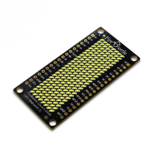
FireBeetle Covers-24×8 LED Matrix
DFRobot FireBeetle is a low-power consumption micro-controller intentionally designed for Internet of Things (IoT). This series micro-controllers aims at IoT node of low-power consumption, attending to build the IoT hardware platform quickly and conveniently. There are three types of FireBeetle, containing Boards (main control), Covers (expansion boards) and related Accessories.
This 24×8 LED Matrix display is special designed for FireBeetle series. It supports low-power consumption mode and scrolling display. With HT1632C high performance LED driver chip, every led has independent register, which makes it easy to drive separately. It integrates a 256KHz RC clock, only 5uA under low-power mode, support 16 scale PWM brightness adjustment. This product also works with the other Arduino micrcontroller like Arduino UNO.
Specification
- Operating Voltage: 3.3~5V
- LED Color: Single color (White/Blue/Yellow/Red/Green)
- Drive Chip: HT1632C
- Working Current: 6~100mA
- Low-power Consumption: 5uA
- RC clock: 256KHz
- Chip Select (CS): D2, D3, D4, D5 selectable
- Serial Data Communication
- Support Arduino Library
- Support Scrolling display
- Interface mode: FireBeetle Series Compatible
- Operating Temperature: -10℃~+85℃
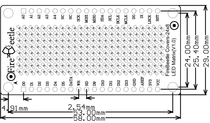
- Dimension: 24 × 58(mm)/0.94 x 2.28(inches)
- Weight: 26g
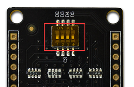
NOTE: FireBeetle Covers-24x8 LED Matrix has 4 CS pin, you can select the CS from the dialing switch, and one FireBeetle can control 4 LED matrix at the same time.
Board Overview
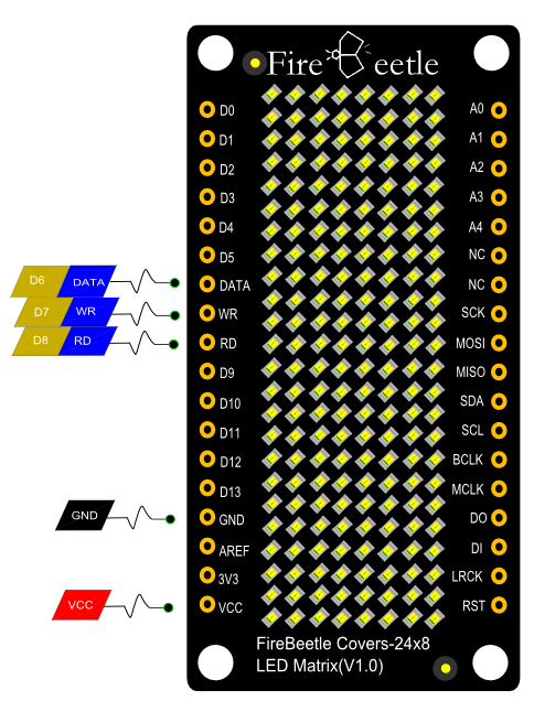
| Num | Label | Description |
|---|---|---|
| 1 | DATA | DATA<——>D6 |
| 2 | WR | WR<——>D7 (Generally Not Used) |
| 3 | CS | CS<——>D2, D3, D4, D5 selectable |
| 4 | RD | RD<——>D8 |
| 5 | VCC | 5V<——>USB; 3.7V<——>Lipo Battery |
Tutorial
In this section,we will demonstrate several example about how to use this LED matrix.
Requirements
-
Hardware
- FireBeetle Board - ESP32 x 1
- FireBeetle Covers-24×8 LED Matrix x1
-
Software
- Arduino IDE Click to Download Arduino IDE from Arduino®
- Arduino Library (Github)
Sample Code: Hello
NOTE: You need use D(x) to call digital I/O pins under Arduino IDE. Or that will be IO(x). CS = D2
#include "DFRobot_HT1632C.h"

#define DATA D6
#define CS D2
#define WR D7
//#define RD 7

DFRobot_HT1632C ht1632c = DFRobot_HT1632C(DATA, WR,CS);

char str[] = "Hello";

void setup() {
  // put your setup code here, to run once:
  ht1632c.begin();
  ht1632c.isLedOn(true);
  ht1632c.clearScreen();
    ht1632c.setCursor(0,0);
  ht1632c.print(str);
}

void loop() {
  // put your main code here, to run repeatedly:

}
Sample Code: Draw Point
You can draw points at any place of the Matrix. X-Y axis coordinate diagram:
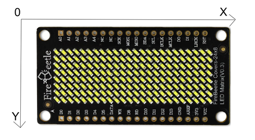
setPixel(x,y):Set coordinates
writeScreen():Draw points
Sample Code:
writeScreen();
Sample Code: Srolling Display
You can use ‘‘setPixel’’ to set the start point, and print str with ms srolling display.
print(str,ms): // str = string; ms = delay time
Smaple code:
#include "DFRobot_HT1632C.h"

#define DATA D6
#define CS D2
#define WR D7

DFRobot_HT1632C ht1632c = DFRobot_HT1632C(DATA, WR,CS);

char str[] = " DFROBOT 2017";

void setup() {
  Serial.begin(115200);
  // put your setup code here, to run once:
  ht1632c.begin();
  ht1632c.isLedOn(true);
  ht1632c.clearScreen();
  delay(500);
}

void loop() {
  // put your main code here, to run repeatedly:
  ht1632c.print(str,50);
  //delay(100);
}
Additional Instruction
FireBeetle Covers-24×8 LED Matrix support Low-power consumption mode, you can use inLowpower function to enter Low-power consumption mode. When it is in Low-power consumption mode, it will close RC clock automatically.
Dimension
FAQ
For any questions, advice or cool ideas to share, please visit the DFRobot Forum.
