Introduction
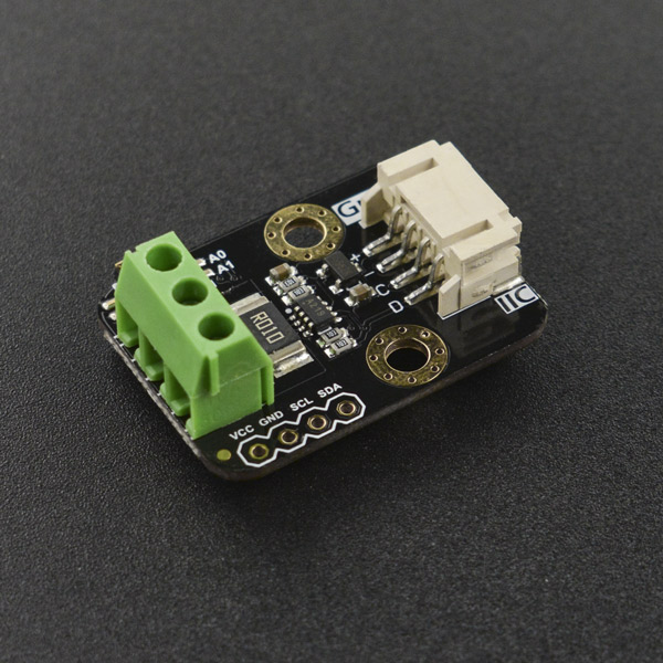
Gravity: I2C Digital Wattmeter is a high-resolution, high-precision, large-scale measurement module that can measure the voltage, current and power of various electronic modules and electrical equipment within 26V 8A, and the maximum relative error is less than ±0.2% (A simple manual calibration is required before usage). It can be used for power consumption or battery life evaluation of solar energy systems, battery, motors, controller or electronic modules.
The module adopts TI INA219 zero temperature drift current/power monitoring chip and 2W high power low temperature drift 10mΩ alloy sampling resistor. The voltage and current resolution can reach 4mV and 1mA respectively. Under the full scale measurement condition, the maximum relative error of voltage and current measurement is lower than ±0.2%. It provides also four I2C addresses that can be configured via the 2P DIP switch. The module accurately measures bi-directional high-side currents (current flowing through the power supply or battery positive), which is especially useful in solar or battery fuel gauge applications where the battery needs to be charged and discharged. This status can be simply determined by positive or negative current readings. In the motor applications, the current can be monitored in real time by monitoring whether the motor current is too large due to overload. In addition, you can use this module to measure the power consumption of various electronic modules or the entire project to evaluate battery life.
Features
- High precision, high resolution, large range, low temperature drift
- Bidirectional current high side measurement
- Compatible with 3.3V/5V controller
- Sophisticated and compact, easy to embed in the project
Application
- Solar Power Management
- Battery Fuel Gauge
- Electronic Module Power Evaluation
Specification
- Input Voltage (VCC) : 3.3V~5.5V
- Voltage Range (IN+ or IN- relative to GND): 0 ~ 26 V
- Voltage Resolution: 4 mV
- Voltage Relative Error: <±0.2% (Typical)
- Current Range: 0 ~ ±8A (Bidirectional current)
- Current Resolution: 1mA
- Current Relative Error: <±0.2% (Typical, manual calibration required)
- Power Range: 0 ~ 206 W
- Power Resolution: 20 mW (Hardware) / 4 mW (Software)
- Quiescent Current: 0.7 mA
- Interface: Gravity I2C (logic level: 0-VCC)
- I2C Address: Four options 0x40, 0x41, 0x44, 0x45
- Dimension: 30.0mm*22.0mm
- Weight: 4g
Board Overview
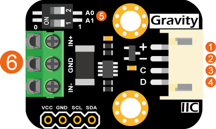
| No. | Label | Description |
|---|---|---|
| 1 | VCC | Power VCC(3.3~5.5V) |
| 2 | GND | Power GND |
| 3 | SCL | I2C clock signal |
| 4 | SDA | I2C data signal |
| 5 | ADDR | I2C address DIP switch |
| 6 | 3P TERMINAL | Voltage and current measurement terminal 3P |
Arduino Tutorial
This tutorial presents a basic usage of the module with Arduino UNO.
Requirements
-
Hardware
- DFRduino UNO R3 (or similar) x 1
- DFRobot Gravity: I2C Digital Wattmeter x 1
- Gravity 4P sensor wire (or Dupont wires) x 1
- High resolution multimeter x1
-
Software
- Arduino IDE
- Download and install the DFRobot_INA219 Library. (About how to install the library?)
Connection Diagram
.png)
Calibration
-
In the actual measurement environment, measurement errors come from many sources. However, for the Gravity: I2C Digital Wattmeter, the voltage measurement does not need to be calibrated, and the current measurement error mainly comes from the error of the resistance of the sampling resistor, which will have a significant impact on the current measurement. If calibration is not performed, the relative error of the maximum current measurement is about 3%. If a single-point linear calibration is performed using a high-precision multimeter or an electronic load, the linearity error of the system can be effectively eliminated, and the maximum relative error can be up to ±0.2%.
-
If you already have a regulated power supply and a DC electronic load on hand, follow the steps below to calibrate the current measurement:
- Connect the Arduino UNO, digital wattmeter module, regulated power supply and DC electronic load as shown below.
- Adjust the output voltage of the power supply to 12V
- Select the constant current mode CC for the electronic load, and set the current to 1.000A.
- Upload the sample code to Arduino UNO.
- Modify the value of the variable "float ina219Reading_mA = 1000;" in the code according to the readings of "Current".
- Upload the sample code to Arduino UNO again.
- Calibration finished.
.png)
- If you don't have a regulated power supply nor a DC electronic load on the hand, follow the steps below to calibrate the current measurement:
- Connect the Arduino UNO, multimeter (switch to amperemeter) and load (gas sensor, motor or LCD screen etc. ) as shown below. It is recommended that the load power consumption should no less than 100mA.
- Upload the following sample code to Arduino UNO.
- Modify the value of the variable "float ina219Reading_mA = 1000;" according to the readings of the serial port print "Current" and "float extMeterReading_mA = 1000;" according to the current readings of the multimeter.
- Upload the sample code to Arduino UNO again.
- Calibration finished.
.png)
- The calibrated parameters "ina219Reading_mA" and "extMeterReading_mA" can now be used in this specific wattmeter module without recalibration for each measurement.
Sample Code
/*!
   file getVoltageCurrentPower.ino
   SEN0291 Gravity: I2C Digital Wattmeter
   The module is connected in series between the power supply and the load to read the voltage, current and power
   The module has four I2C, these addresses are:
   INA219_I2C_ADDRESS1  0x40   A0 = 0  A1 = 0
   INA219_I2C_ADDRESS2  0x41   A0 = 1  A1 = 0
   INA219_I2C_ADDRESS3  0x44   A0 = 0  A1 = 1
   INA219_I2C_ADDRESS4  0x45   A0 = 1  A1 = 1

   Copyright    [DFRobot](https://www.dfrobot.com), 2016
   Copyright    GNU Lesser General Public License
   version  V0.1
   date  2019-2-27
*/

#include <Wire.h>
#include "DFRobot_INA219.h"

DFRobot_INA219_IIC     ina219(&Wire, INA219_I2C_ADDRESS4);

// Revise the following two paramters according to actula reading of the INA219 and the multimeter
// for linearly calibration
float ina219Reading_mA = 1000;
float extMeterReading_mA = 1000;

void setup(void)
{
    Serial.begin(115200);
    while(!Serial);

    Serial.println();
    while(ina219.begin() != true) {
        Serial.println("INA219 begin faild");
        delay(2000);
    }
    ina219.linearCalibrate(ina219Reading_mA, extMeterReading_mA);
    Serial.println();
}

void loop(void)
{
    Serial.print("BusVoltage:   ");
    Serial.print(ina219.getBusVoltage_V(), 2);
    Serial.println("V");
    Serial.print("ShuntVoltage: ");
    Serial.print(ina219.getShuntVoltage_mV(), 3);
    Serial.println("mV");
    Serial.print("Current:      ");
    Serial.print(ina219.getCurrent_mA(), 1);
    Serial.println("mA");
    Serial.print("Power:        ");
    Serial.print(ina219.getPower_mW(), 1);
    Serial.println("mW");
    Serial.println("");
    delay(1000);
}
Results
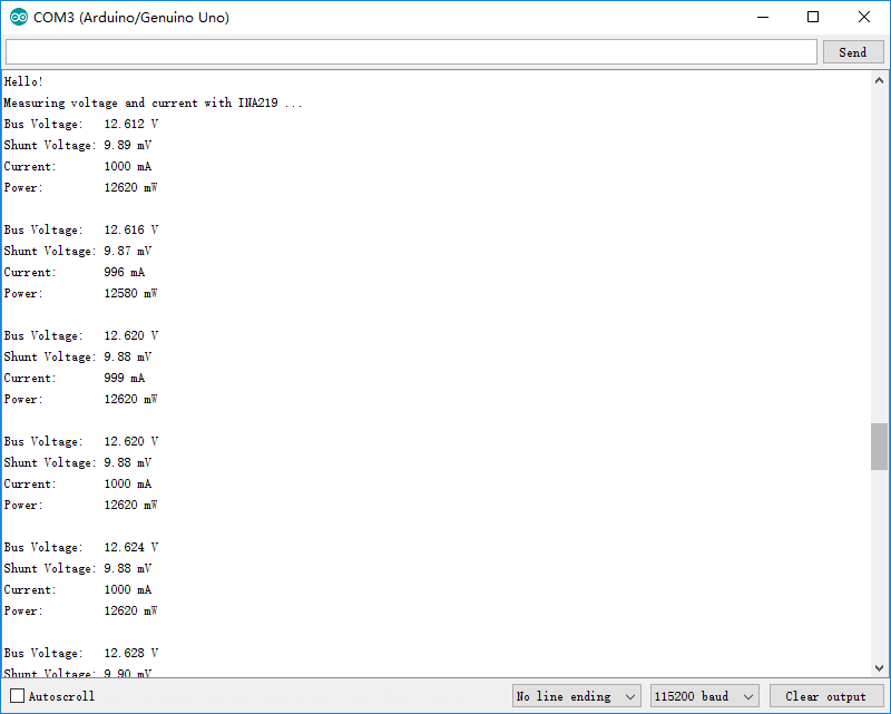
- The module prints four parameters every 1s:
- ShuntVoltage: Voltage of the sampling resistor, IN+ to NI-.
- BusVoltage: Voltage of IN- to GND.
- Current: Current flows across IN+ and IN-. If the current flows from IN+ to IN-, the reading is positive. If the current flows from IN- to IN+, the reading is negative.
- Power: The product of "BusVoltage" and "Current", that is, power. The power resolution read directly from the module is 20mW (hardware mode). If the power is obtained by using the statement "Power = BusVoltage*Current;", the resolution can be increased to 4mW (software mode).
-
The module can be configured as one of four different I2C addresses by DIP switch. Accordingly, change the parameter "INA219_I2C_ADDRESSx" of "ina219.setI2cAddr(INA219_I2C_ADDRESS4);", where x can be 1, 2, 3 or 4. The mapping of DIP switch and the I2C address parameter is as follow:
- INA219_I2C_ADDRESS1: 0x40, A0=0, A1=0
- INA219_I2C_ADDRESS2: 0x41, A0=1, A1=0
- INA219_I2C_ADDRESS3: 0x44, A0=0, A1=1
- INA219_I2C_ADDRESS4: 0x45, A0=1, A1=1
-
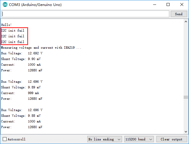
If the I2C fails due to the following reasons, "I2C init fail" is printed.
- The I2C wiring SCL and SDA are not properly connected.
- The I2C address (DIP switch) does not match the I2C address parameter.
-
When the DIP switch is properly configured, the "Measuring voltage and current with INA219 ..." is printed and the readings resume.
Raspberry Pi Tutorial
This tutorial presents a basic usage of the module with Raspberry Pi.
Requirements
-
Hardware
- Raspberry Pi 3 Model B (or similar) x 1
- DFRobot Gravity: I2C Digital Wattmeter Sensor x 1
- Gravity 4P sensor wire (or Dupont wires) x 1
- High resolution multimeter x1
-
Software
- RASPBIAN
- Download and install the DFRobot_INA219 RaspberryPi library.
Connection Diagram
.png)
Installation
- Start the I2C interface of the Raspberry Pi. If it is already open, skip this step. Open Terminal, type the following command, and press Enter:
pi@raspberrypi:~ $ sudo raspi-config
- Then use the up and down keys to select “5 Interfacing Options” -> “P5 I2C” and press Enter to confirm “YES”. Reboot the Raspberry Pi.
- Installing Python libraries and git (networking required). If it is already installed, skip this step. In the Terminal, type the following commands, and press Enter:
pi@raspberrypi:~ $ sudo apt-get update
pi@raspberrypi:~ $ sudo apt-get install build-essential python-dev python-smbus git
- Download the driver. In Terminal, type the following commands, and press Enter:
pi@raspberrypi:~ $ git clone https://github.com/DFRobot/DFRobot_INA219.git
Run Sample Code
- Connect the module to the Raspberry Pi according to the connection diagram. The I2C address defaults to 0x45, corresponding to "_INA219_I2C_ADDRESS4" in the code. If the I2C address needs to be modified, configure A0 and A1 to 0 or 1 respectively by the DIP switch on the module, and modify "_INA219_I2C_ADDRESS_x", the second parameter of "ina=INA219(1, _INA219_I2C_ADDRESS4)" in “getVoltageCurrentPower.py”. x can be 1, 2, 3 or 4. The mapping of DIP switch and the I2C address parameters are as follow:
- _INA219_I2C_ADDRESS1: 0x40, A0=0, A1=0
- _INA219_I2C_ADDRESS2: 0x41, A0=1, A1=0
- _INA219_I2C_ADDRESS3: 0x44, A0=0, A1=1
- _INA219_I2C_ADDRESS4: 0x45, A0=1, A1=1
- Install DFRobot_INA219 Raspberry Pi library. In the Terminal, type the following commands and press Enter to run the sample code:
pi@raspberrypi: $ cd ~/DFRobot_INA219/RaspberryPi/Python/example
pi@raspberrypi:~/DFRobot_INA219/RaspberryPi/Python/example $ python getVoltageCurrentPower.py
Results
-
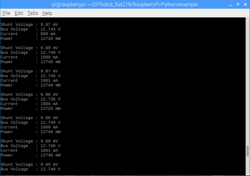
The module prints four parameters every 1s:
- ShuntVoltage: Voltage of the sampling resistor, IN+ to NI-.
- BusVoltage: Voltage of IN- to GND.
- Current: Current flows through IN+ and IN-. If the current flows from IN+ to IN-, the reading is positive. If the current flows from IN- to IN+, the reading is negative.
- Power: The product of "BusVoltage" and "Current", that is, power. The power resolution read directly from the module is 20mW (hardware mode). If the "BusVoltage" (resolution 4mV) and "Current" (resolution 1mA) are separately read, the power resolution obtained by using the statement "Power = BusVoltage*Current;" can be increased to 4mW (software mode).
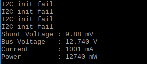
- If the I2C fails due to the following reasons, "I2C init fail" is printed.
- The I2C wiring SCL and SDA are not properly connected.
- The I2C address (DIP switch) does not match the I2C address parameter.
- When the DIP switch is properly configured, the readings resume.
Applications
-
Measuring power consumption electronic modules
Many electronic modules do not clearly indicate the operating current of the module. The following figure (taking the SEN0161-V2 Gravity: Analog pH Sensor as an example) shows how to measure the power consumption of the analog pH sensor by connecting the Gravity: I2C digital power meter between the VCC of the controller and the sensor in series. Such consumption measurement is simpler and more intuitive than measuring current and voltage by using the multimeter separately.
.png)
-
Monitor the power consumption of the solar panel, battery and outputs in a solar system
In a typical solar system as shown below (taking the Solar Power Management Module For 12V Lead Acid Battery as an example). Four Gravity: I2C digital Wattmeter are used to monitor the voltage, current and power of the solar panel, battery and two output terminals OUT1 and OUT2, respectively. Each meter is configured by a DIP switch to a different I2C address. They are connected in parallel to the same controller, which records the energy data of each meters (nodes).
For the solar panel, in addition to the voltage, current and power, we maybe more concern about the accumulated electrical energy generated over a period of time. This period may be a day, or it may be several weeks or even months. The time recording can be achieved by adding an RTC module to the controller. Accumulated Power Generation can be obtained by integrating the power with time. For example, sum P power (W) every 1s to obtain the E (electrical) energy (J). This can be converted into another unit Wh by E/3600, or kWh by E / (3.6 × 10 ^ 6) .
For the battery, the wattmeter measures the capacity of the battery by measuring the charge and discharge current. Note that IN+ is directly connected to the positive terminal of the battery, and IN- is connected to the positive input terminal of the BAT IN of the power management module. When the reading is positive, current flows from IN+ to IN-, indicating that the battery is discharging. When the current reading is negative, current flows from IN- to IN+, indicating that the battery is charging. Therefore, the charge and discharge state of the battery can be determined by the positive and negative values of the current. Capacity (Ah), remaining power of the battery is another parameter we may concern. Similar to recording the Accumulated Power Generation, integrating the current with time to get the Capacity (Ah). To obtain a more accurate capacity of the battery, battery can be first fully charged with the power management module and a laptop power adapter (rated output voltage 19V or 20V and power at least 65W). Then, the battery is discharged at one of the OUT terminal until the output is turned off. The Capacity (Ah) is then recorded using the wattmeter at the battery side. Of course, the battery capacity is also related to a number of factors such as the discharge current, the temperature, and the number of cycles the battery has been used. However, the capacity obtained by this method is much more accurate than the nominal capacity of the battery.
For the output terminal OUT, the Accumulated Power Consumption is another power statistic worthy of attention, and its calculation is similar to Accumulated Energy Generation.
It is worth noting that Accumulated Energy Generation is usually larger than the sum of the other three Accumulated Power Consumption (assuming the battery is always charging, that is, all three are sourced from solar panels). Excluding the measurement error of the wattmeter, the difference between the two mainly comes from various types of wire and conversion loss, such as: loss of the power management module, loss of the module sampling resistor, and loss of the connection wire and the terminal contact resistor etc. Users can take these losses into account according to the actual application scenarios.
.png)
Note: Since most solar management modules have battery protection that disconnects GND from BAT-. If you connect BAT- to GND as shown in the above diagram to monitor the battery level, it will result in BAT- not being able to disconnect GND and disable the battery protection circuit of the solar management module.
FAQ
For any questions, advice or cool ideas to share, please visit the DFRobot Forum.
