Introduction
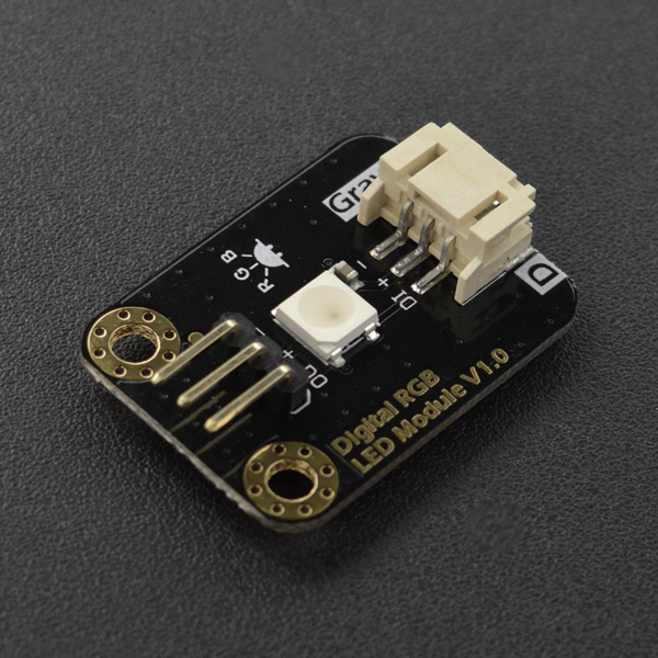
Gravity: Digital RGB LED Module is a cascadable single RGB LED module compatible with RGB LED strip. The Gravity interface provides a more elegant manner for the connections between modules and most of mainstream controllers such as Arduino, micro:bit, Firebeetle Series, LattePanda, and Raspberry Pi with an abundant kinds of DFRobot IO expansion shield. Compared to the traditional RGB LED module, where three control signal pins are required for a single LED, this module only needs one signal pin for all LEDs in cascade. Thanks to such individual module design, RGB LED strip built by such independent modules can realize extremely low power consumption per meter compared to traditional RGB LED strip. And such feature makes it possible to cascade more than 100 modules with a total length up to several tens of meters but power requirement no more than 5V 2A. This also makes it much simpler and more flexible to configure the length of an RGB LED strip, without the need of cutting a RGB LED strip or soldering every LED pieces.
The module adopts the same high-brightness RGB LED in the traditional RGB LED strip, inheriting its excellent display performance and is fully compatible with the driving circuit or program. This requires little changes for existing programs to shift from RGB LED strip to RGB LED module string. Have fun with this tiny RGB LED module by cool effects of flashing, rainbow, even letters, pictures or animations.
Features
- Excellent display performance, quality high-brightness WS2812 REB LED
- Extremely long cascading length, low unit length power consumption
- High compatibility, compatible with 3.3V/5V controller, RGB LED strip drivers or programs
- Standard connector, easy setup without cutting or soldering
Application
- Holiday Decorations
- Signal Indicator
Specification
- LED Type: WS2812 RGB 5050 LED
- Input Voltage: 3.3V~5.5V
- Maximum Current: 48mA
- Quiescent Current: 0.7mA
- Interface: Gravity 3P Digital
- Dimension: 30.0mm*22.0mm / 1.18*0.87 in
Board Overview

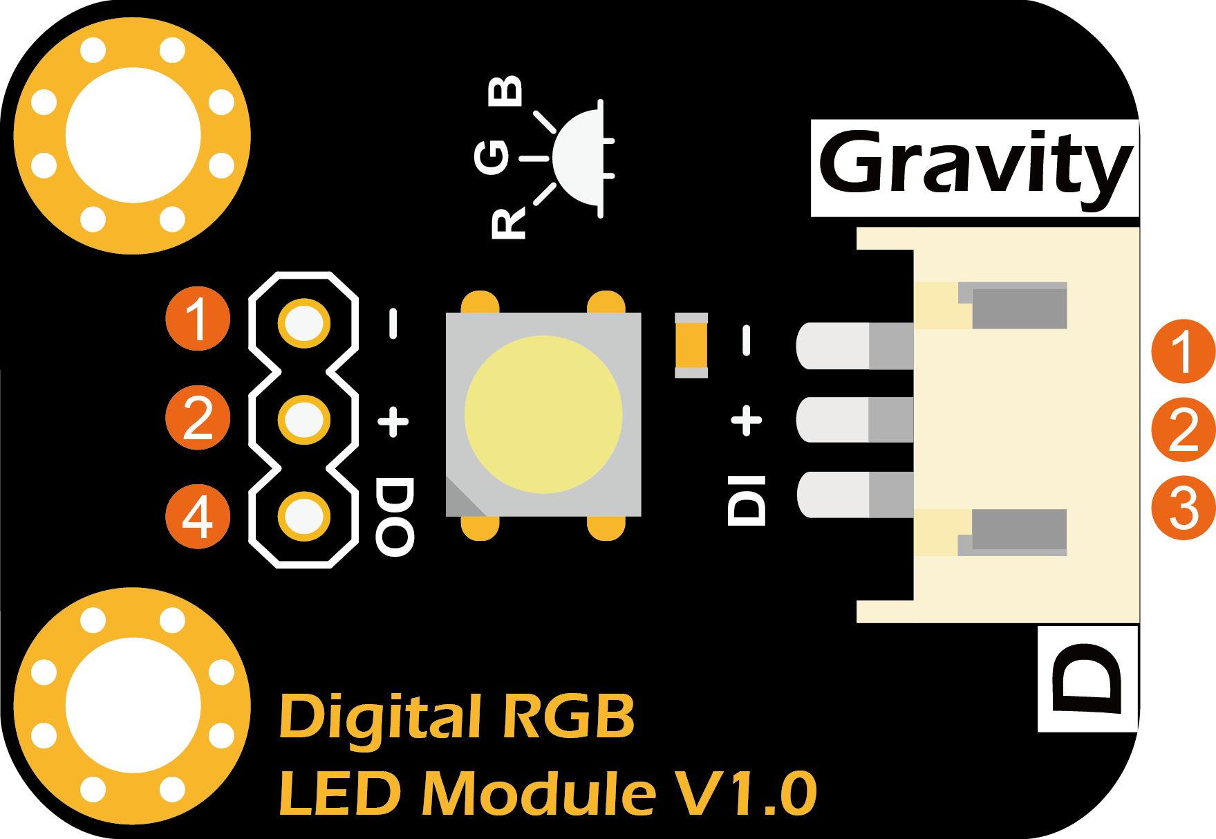
| No. | Label | Description |
|---|---|---|
| 1 | - | Power supply GND |
| 2 | + | Power supply VCC(3.3~5.3V) |
| 3 | DI | Control data signal input |
| 4 | DO | Control data signal output |
Arduino Tutorial
This tutorial presents a basic usage of the module with Arduino UNO.
Requirements
-
Hardware
- DFRduino UNO R3 (or similar) x 1
- Gravity: Digital RGB LED Module x 1
- Gravity 3P digital sensor cable (or Dupont wires) x 1
-
Software
Connection Diagram

Sample Code
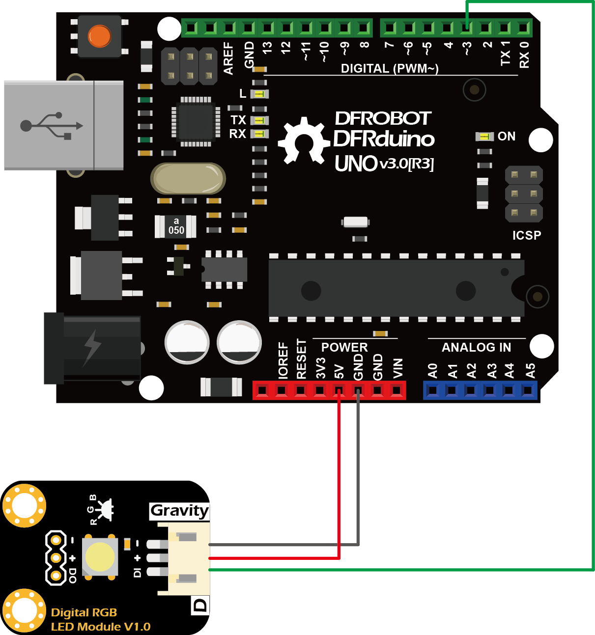
- Connect the module to the Arduino according to the connection diagram.
- Install "Adafruit NeoPixel Library".
- Open the Arduino IDE and upload the following sample code to Arduino UNO.
#include <Adafruit_NeoPixel.h>

#define PIN_LED 3     // Control signal, connect to DI of the LED
#define NUM_LED 1     // Number of LEDs in a strip

// Custom colour1: Yellow
#define RED_VAL_1       255
#define GREEN_VAL_1     255
#define BLUE_VAL_1      0

// Custom colour2: Purple
#define RED_VAL_2       255
#define GREEN_VAL_2     0
#define BLUE_VAL_2      255

// Custom colour3: Cyan
#define RED_VAL_3       0
#define GREEN_VAL_3     255
#define BLUE_VAL_3      255

// Custom colour4: White
#define RED_VAL_4       255
#define GREEN_VAL_4     255
#define BLUE_VAL_4      255

Adafruit_NeoPixel RGB_Strip = Adafruit_NeoPixel(NUM_LED, PIN_LED, NEO_GRB + NEO_KHZ800);

void setup() {
  RGB_Strip.begin();
  RGB_Strip.show();
  RGB_Strip.setBrightness(128);    // Set brightness, 0-255 (darkest - brightest)
}

void loop() {

  colorWipe(RGB_Strip.Color(255, 0, 0), 1000);  // Red
  colorWipe(RGB_Strip.Color(0, 255, 0), 1000);  // Green
  colorWipe(RGB_Strip.Color(0, 0, 255), 1000);  // Blue

  colorWipe(RGB_Strip.Color(RED_VAL_1, GREEN_VAL_1, BLUE_VAL_1), 1000);   // Custom colour1: Yellow
  colorWipe(RGB_Strip.Color(RED_VAL_2, GREEN_VAL_2, BLUE_VAL_2), 1000);   // Custom colour2: Purple
  colorWipe(RGB_Strip.Color(RED_VAL_3, GREEN_VAL_3, BLUE_VAL_3), 1000);   // Custom colour3: Cyan
  colorWipe(RGB_Strip.Color(RED_VAL_4, GREEN_VAL_4, BLUE_VAL_4), 1000);   // Custom colour4: White

  rainbow(20);  // Rainbow
}

// Fill the dots one after the other with a color
void colorWipe(uint32_t c, uint16_t wait) {
  for (uint16_t i = 0; i < RGB_Strip.numPixels(); i++) {
    RGB_Strip.setPixelColor(i, c);
    RGB_Strip.show();
    delay(wait);
  }
}

void rainbow(uint8_t wait) {
  uint16_t i, j;

  for (j = 0; j < 256; j++) {
    for (i = 0; i < RGB_Strip.numPixels(); i++) {
      RGB_Strip.setPixelColor(i, Wheel((i + j) & 255));
    }
    RGB_Strip.show();
    delay(wait);
  }
}

// Input a value 0 to 255 to get a color value.
// The colours are a transition r - g - b - back to r.
uint32_t Wheel(byte WheelPos) {
  if (WheelPos < 85) {
    return RGB_Strip.Color(WheelPos * 3, 255 - WheelPos * 3, 0);
  } else if (WheelPos < 170) {
    WheelPos -= 85;
    return RGB_Strip.Color(255 - WheelPos * 3, 0, WheelPos * 3);
  } else {
    WheelPos -= 170;
    return RGB_Strip.Color(0, WheelPos * 3, 255 - WheelPos * 3);
  }
}
Results
-
The module first displays the three primary colors "red", "green", "blue", and then displays four custom mixed colors "yellow", "purple", "green", "white", each color is displayed for 1 second, and then the "Rainbow" effect. This pattern will repeat forever.
-
To adjust LED brightness, change the value "128" in the function
RGB_Strip.setBrightness(128); // Set brightness, 0-255 (darkest - brightest)
Applications
Employ the drawing software palette to display a desired color
In the sample code above, we set a color by first configuring the values of three primary colors
// Custom colour
#define RED_VAL       255
#define GREEN_VAL     255
#define BLUE_VAL      255
and then call the function
Color (RED_VAL, GREEN_VAL, BLUE_VAL); // Set brightness, 0-255 (darkest - brightest)
But how to determine these RGB value for a specific color. This can be simply achieved by using drawing software "Paint" of the OS (take WIN10 as an example). The steps are as follows:
- Run “Paint"
- Select "Edit Color".
- Select the desired color in the palette.
- Fill the displayed RGB values into the function "Color (RED_VAL, GREEN_VAL, BLUE_VAL)".
- Recompile the upload the code.
.png)
Module cascade
- Wiring: The module reserves a 2.54mm-3P pad for cascading. The user can first solder the 3P bent header and then use the Gravity 3P digital sensor cable for connection. Insert one end of the cable, PH2.0-3P white male connector, to the PH2.0-3P white female connector of the module, and the other end, black 2.54mm-3P female header connector, to the 3P bent header of the previous module. Connect the modules in such way one by one to forming a string of lights. As shown in the figure below, the "+", "-", and "DO" are connected to "+", "-", and "DIN" respectively of the next module.
- Code: The sample code applies to a single module. To use in cascade, you need to change the value "1" in the sample code (as shown below) to the number of modules to be cascaded. Otherwise no matter how many module is cascaded, only the first one will light up. For example, a RGB LED strip is made up of 32 modules. The value should be changed to "32".
#define NUM_LED 1 // Number of LEDs in a strip
- Power consumption and length estimation: The length of every section of a RGB LED string (Module + Gravity 3P Digital Sensor Cable) is about 32cm, which greatly reduces the number of LEDs and power consumption per meter compared to the ordinary RGB LED strip. Under the same power supply, the entire strip can be extended to several tens of meters. If modules are powered by 5V, set to white color and brightest, power consumption can be up to 48mA. Under this condition, if the strip is powered by the USB of the Arduino whose maximum output capacity is 500mA (determined by the Arduino internal self-recovery fuse). Such configuration can drive about 10 modules with a total length of about 3.2m. If the Arduino is externally powered by 7-12V (using a power adapter, 2s 7.4V or 3s 11.1V lithium battery), its maximum output capacity is 800mA (determined by Arduino internal LDO). Such configuration can drive about 16 modules with a total length of about 5m. If the Arduino is externally powered by IO sensor expansion board V7.1 , where the servo external terminal SERVO_PWR is powered by 5V 2A AC adapter, such configuration can drive 41 modules with a length of about 13m. The estimation above provides the lower limit (worse case) of the cascading number from the perspective of the supply current and the maximum power consumption of the module. The actual maximum cascading number is affected by the actual power consumption (color or brightness) and the voltage loss in cable (the voltage is dropping through the cable). Usually, the power supply voltage of the last module of the string should not be lower than 3.3V. The number and length of the cascade can be much higher than the estimated value above. By properly decreasing brightness, the maximum cascading number can be greatly increased.
.png)
FAQ
For any questions, advice or cool ideas to share, please visit the DFRobot Forum.
