Introduction
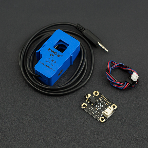
When you want to measure AC current, it is common to have trouble cutting the wires, wiring or soldering. The Gravity: Analog AC Current Sensor comes to the rescue, eliminating the need to cut wires or reconnect circuits. Simply clamp the AC transformer probe on the AC line, and then plug the 3.5mm headphone jack into the signal conversion module to read the current AC current value. The analog output is designed to be compatible with 3V3/5V micro-controller. It can be conveniently used for AC current measurement to monitor AC motors, lighting equipment, air compressors, etc.
Specification
-
AC Current Signal Conversion Module
- Input Voltage (VCC): 3.3V - 5.5V
- Interface: Gravity Analog (PH2.0-3P,analog voltage output 0.2-2.8VDC)
- AC Voltage Input Range: 0-1V (AC RMS)
- Relative Error: ±4%
- Dimension: 32 × 27 mm /1.26 × 1.06 in
- Weight: 5 g
-
Open Type AC Transformer Probe
- AC Current Range: 0 - 5A (SEN0287), 0 - 10A(SEN0288), 0 - 20A(SEN0211)
- Signal Output (standard Φ3.5mm 3P plug): 0-1V AC voltage, linear corresponding range 0-5A, 0-10A, 0-20A
- Accuracy: ±1%
- Non-linearity: ≤±0.2%
- Frequency Range: 50Hz ~ 1kHz
- Cable Length: 1 m
- Working Temperature: -25 ℃ ~ +70 ℃
- Opening Size: 13 × 13 mm / 0.51 × 0.51 in
- Weight: 50 g
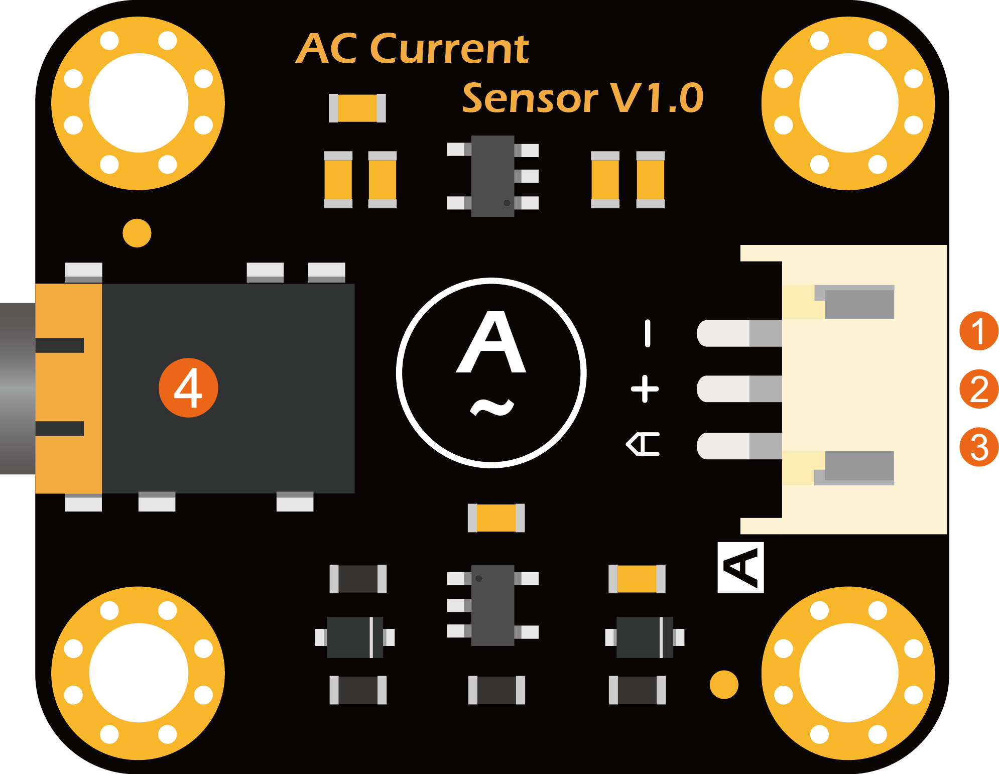
Board Overview

| LABEL | NAME | Function Description |
|---|---|---|
| 1 | - | GND |
| 2 | + | Power Input (3.3V-5.5V) |
| 3 | A | Signal Output (0.2-2.8VDC) |
| 4 | Φ3.5mm 3P plug | AC Transformer Input Signal |
Tutorial
This tutorial will demonstrate how to use the AC transformer probe and AC sensor module to detect AC current.
Requirements
- Hardware
- Arduino UNO or simliar x1
- AC Current Signal Conversion Module x1
- Open Type AC Transformer Probe x1
- LCD Keypad Shield For Arduino x1
- Gravity-3P Analog Sensor Cable x1
- Software
- Arduino IDE V1.6.5 Click to Download Arduino IDE from Arduino®
Connection Diagram
.png)
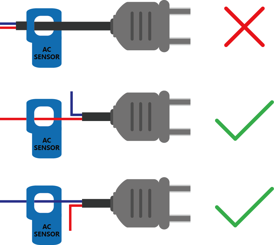
The AC transformer probe can only clamp to one of the AC wire. It cannot be clamped both at the same time!

Sample Code
- Connect the module to the A2 port of the Arduino UNO according to the connection diagram.
- Modify the parameters of #define ACTectionRange 20; in the sample code according to the AC transformer range used. For example, if the AC transformer range is 5A (SEN0287), change this parameter to 5.
- Upload the sample program below.
- Turn on the serial port monitoring, set the baud rate to 115200, and observe the serial printed data.
About Calibration
Since the analog reading is affected by the accuracy of the reference voltage. For a more accurate reading, use a high-precision multimeter to measure the analog reference voltage of the controller (usually the same as the supply voltage) and modify the #define VREF 5.0 parameter in the sample code below to complete the calibration.
/*!
 * @file readACCurrent.
 * @n This example reads Analog AC Current Sensor.

 * @copyright   Copyright (c) 2010 DFRobot Co.Ltd (https://www.dfrobot.com)
 * @licence     The MIT License (MIT)
 * @get from https://www.dfrobot.com

 Created 2016-3-10
 By berinie Chen <[email protected]>

 Revised 2019-8-6
 By Henry Zhao<[email protected]>
*/

const int ACPin = A2;         //set arduino signal read pin
#define ACTectionRange 20;    //set Non-invasive AC Current Sensor tection range (5A,10A,20A)

// VREF: Analog reference
// For Arduino UNO, Leonardo and mega2560, etc. change VREF to 5
// For Arduino Zero, Due, MKR Family, ESP32, etc. 3V3 controllers, change VREF to 3.3
#define VREF 5.0

float readACCurrentValue()
{
  float ACCurrtntValue = 0;
  float peakVoltage = 0;
  float voltageVirtualValue = 0;  //Vrms
  for (int i = 0; i < 5; i++)
  {
    peakVoltage += analogRead(ACPin);   //read peak voltage
    delay(1);
  }
  peakVoltage = peakVoltage / 5;
  voltageVirtualValue = peakVoltage * 0.707;    //change the peak voltage to the Virtual Value of voltage

  /*The circuit is amplified by 2 times, so it is divided by 2.*/
  voltageVirtualValue = (voltageVirtualValue / 1024 * VREF ) / 2;

  ACCurrtntValue = voltageVirtualValue * ACTectionRange;

  return ACCurrtntValue;
}

void setup()
{
  Serial.begin(115200);
  pinMode(13, OUTPUT);

}

void loop()
{
  float ACCurrentValue = readACCurrentValue(); //read AC Current Value
  Serial.print(ACCurrentValue);
  Serial.println(" A");
  digitalWrite(13, HIGH);
  delay(500);
  digitalWrite(13, LOW);
  delay(500);
}
Connection Diagram with LiquidCrystal
.png)
Sample Code with LiquidCrystal
/*!
 * @file readACCurrent_LCD.
 * @n This example reads Analog AC Current Sensor and display on the LCD.

 * @copyright   Copyright (c) 2010 DFRobot Co.Ltd (https://www.dfrobot.com)
 * @licence     The MIT License (MIT)
 * @get from https://www.dfrobot.com

 Created 2016-3-10
 By berinie Chen <[email protected]>

 Revised 2019-8-6
 By Henry Zhao<[email protected]>
*/

#include <LiquidCrystal.h>

LiquidCrystal lcd(8, 9, 4, 5, 6, 7);        // select the pins used on the LCD panel

const int ACPin = A2;         //set arduino signal read pin
#define ACTectionRange 20;    //set Non-invasive AC Current Sensor tection range (5A,10A,20A)

// VREF: Analog reference
// For Arduino UNO, Leonardo and mega2560, etc. change VREF to 5
// For Arduino Zero, Due, MKR Family, ESP32, etc. 3V3 controllers, change VREF to 3.3
#define VREF 5.0

float readACCurrentValue()
{
  float ACCurrtntValue = 0;
  float peakVoltage = 0;
  float voltageVirtualValue = 0;  //Vrms
  for (int i = 0; i < 5; i++)
  {
    peakVoltage += analogRead(ACPin);   //read peak voltage
    delay(1);
  }
  peakVoltage = peakVoltage / 5;
  voltageVirtualValue = peakVoltage * 0.707;    //change the peak voltage to the Virtual Value of voltage

  /*The circuit is amplified by 2 times, so it is divided by 2.*/
  voltageVirtualValue = (voltageVirtualValue / 1024 * VREF ) / 2;

  ACCurrtntValue = voltageVirtualValue * ACTectionRange;

  return ACCurrtntValue;
}

void setup()
{
  Serial.begin(115200);
  lcd.begin(16, 2);                       // start the library
  pinMode(13, OUTPUT);
}

void loop()
{
  lcd.setCursor(3, 0);
  float ACCurrentValue = readACCurrentValue(); //read AC Current Value
//  Serial.println(ACCurrentValue);
  lcd.print("AC CURRENT");
  lcd.setCursor(5, 1);
  lcd.print(ACCurrentValue);
  lcd.print("  A");
  digitalWrite(13, HIGH);
  delay(500);
  digitalWrite(13, LOW);
  delay(500);
}
FAQ
For any questions, advice or cool ideas to share, please visit the DFRobot Forum.
