Introduction
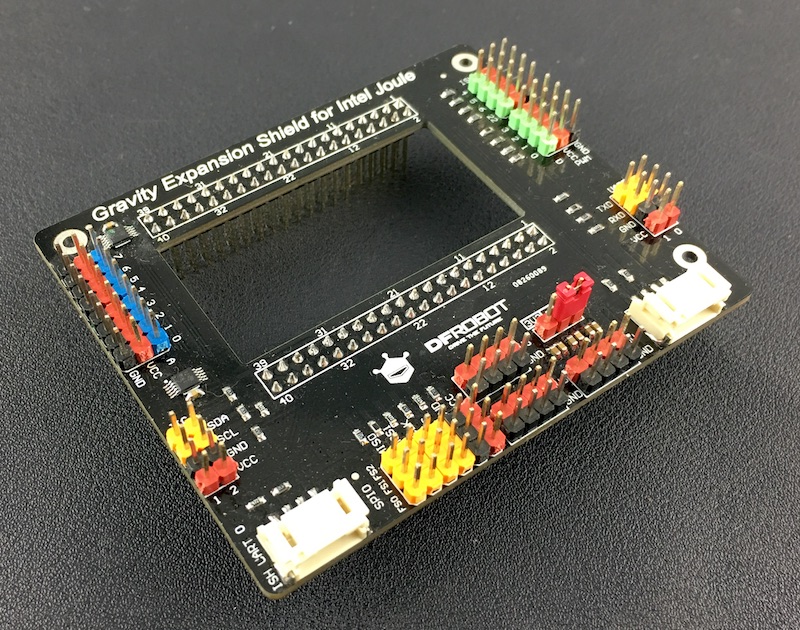
Try to use Intel Joule with hundreds of sensors and modules. This will be a really good choice.
Feature
- Deprecated shield board for Intel Joule
- Onboard ADC support
- Easy-to-use DFRobot Gravity connecter
- 3.3V and 5V multi-voltage support
Specification
| - | - |
|---|---|
| Digital I/O: | 8 |
| PWM: | 4 |
| Analog I/O: | 8 (using onboard chip via I2C) |
| SPI: | 1 (with 3 chip select pins) |
| I2C: | 3 |
| UART: | 3 |
| Power Output: | 5V & 3.3V & 1.8V |
| Gravity I2C: | 1 |
| Gravity UART: | 1 |
| Module Voltage: | 5V or 3.3V |
| Size: | 86mm * 71mm * 22mm |
| Weight: | 30g |
Board Overview
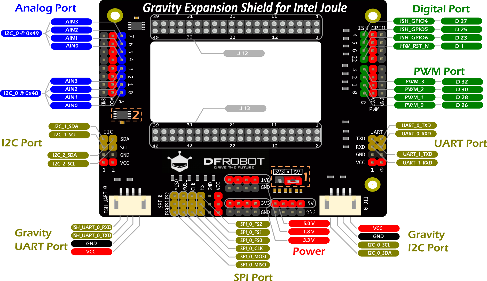
| NOTE: To get the right pin number: GPIO Pin 4 on board >> ISH_GPIO4 >> D 27, so the pin number in the code should be 27. PWM Pin 3 on board >> PWM_3 >> D 32, so the pin number in the code should be 32 |
|---|
| Details about the board | ||

| Jumper cap for switching voltage | All the red pin named "VCC" on this board will affect. umper on 3V3 side: VCC = 3.3V Jumper on 5V side: VCC = 5V |

| ADC chip: ADS1115 | Two ADS1115 carry 8 analog pins altogether and they are connected on I2C Bus 0. I2C Address: 0x48 >> A0 ~ A3 I2C Address: 0x49 >> A4 ~ A7 Also see "Analog Read Demo" below. |
| NOTE: Other pins's function on Joule, you can check them here. |
|---|
Get Started to blink a LED
In this section you will create your first project with Intel Joule -- Blink a LED.
Tools needed
| - | - |
|---|---|
| Intel Joule Developer Kit | x1 |
| Gravity Expansion Shield for Intel Joule | x1 |
| Gravity Sensor Kit for Intel Joule | x1 |
| Wall Adapter Power Supply 7.5VDC 1A | x1 |
Intel Joule Setup
- Please follow the <Intel® Joule Module User Guide> for the setup steps. It is a deprecated and detailed guide by Intel.
| NOTE: This Demo prefers "Reference Linux* OS for IoT" instead of Ubuntu or Windows 10 IOT. You can keep your OS updated via ,If there is something wrong with your board, you can always flash the BIOS to reset your board |
|---|
Requirements
-
Hardware
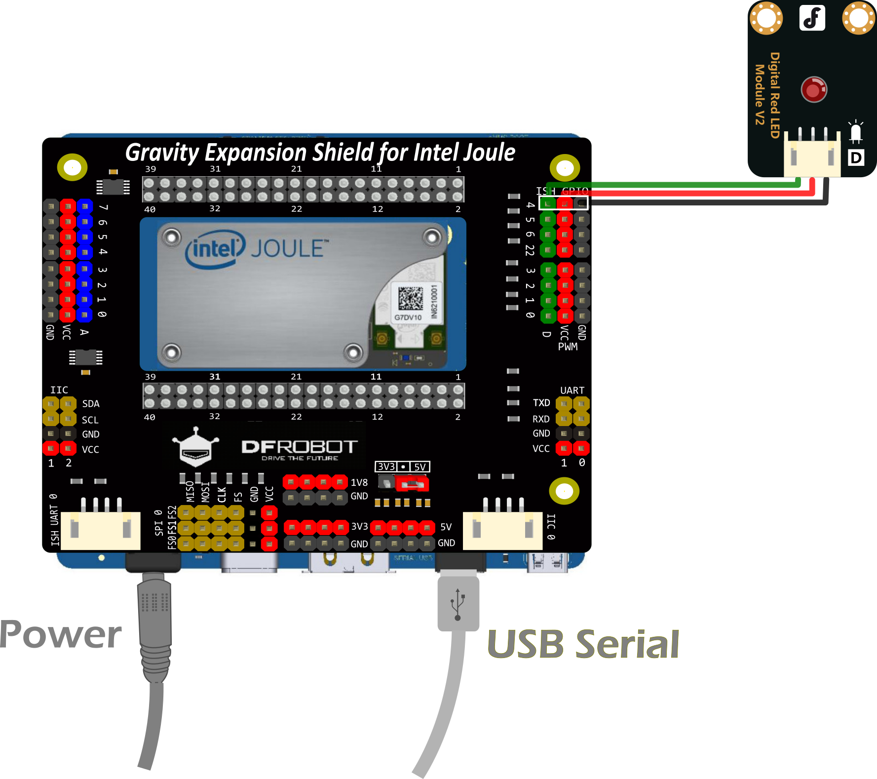
- Plug Gravity Expansion Shield onto Intel Joule board.
- Connect the power supply
- Connect usb serial port to your computer.
- Find the "Gravity:Digital RED LED Light Module" in the "Gravity Sensor kit for Intel Joule" and connect to GPIO pin 4 as the hardware connection showed above.
-
Software
There is a known software issue in MRAA which prevents GPIO working properly. We reported it to Intel and they solved it quickly. However, it will not be released until fully tested.
Although It is a better idea to wait for the the fully tested version, if you are willing to have a try, you can get here and update the latest version.
- Login your Joule via Putty or other serial tools.
- Create a Node JS example using vi.
vi blink.js
NOTE: Tip to get the right pin number: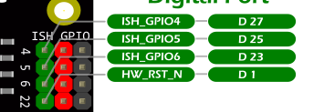 For example: GPIO Pin 4 on board >> ISH_GPIO4 >> D 27, so the pin number in the code should be 27. Please check the Board Overview for other pins. For example: GPIO Pin 4 on board >> ISH_GPIO4 >> D 27, so the pin number in the code should be 27. Please check the Board Overview for other pins. |
var m = require('mraa'); //require mraa
console.log('MRAA Version: '   m.getVersion()); //write the mraa version to the console

var myLed = new m.Gpio(27); //Corresponding to ISH_GPIO4
myLed.dir(m.DIR_OUT); //set the gpio direction to output
var ledState = true; //Boolean to hold the state of Led

function periodicActivity()
{
  myLed.write(ledState?1:0); //if ledState is true then write a '1' (high) otherwise write a '0' (low)
  ledState = !ledState; //invert the ledState
  setTimeout(periodicActivity,1000); //call the indicated function after 1 second (1000 milliseconds)
}

periodicActivity(); //call the periodicActivity function
- Run the node sample in the bash.
node blink.js
- The LED starts to blink.
to stop running the demo. - You have done the first project on Intel Joule. Well Done!
Connection Diagram
Sample Code
void setup() {
  // put your setup code here, to run once:

}

void loop() {
  // put your main code here, to run repeatedly:

}
Analog Read Demo
In this section, you will know how to use the onboard ADS1115. For this demo, we assume that you have successfully finished the blink demo above.
Hardware Connection
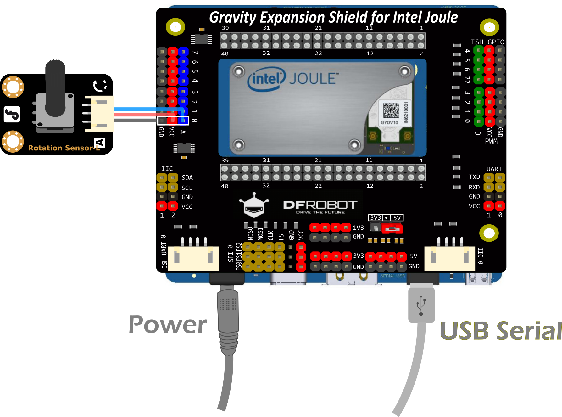
Hardware
Find the "Gravity:Analog Rotation Potentiometer Sensor V1 For Arduino" module in the "Gravity Sensor kit for Intel Joule" and connect to Analog pin 0 as the hardware connection showed above.
Software
Run the following code to get the analog result.
var mraa = require('mraa');
var version = mraa.getVersion();

if (version >= 'v0.6.1') {
    console.log('mraa version ('   version   ') ok');
}
else {
    console.log('mraa version('   version   ') is old - this code may not work')
}

var ads1115 = new mraa.I2c(0);

//A0~A3
ads1115.address(0x48)

//A4~A7
// ads1115.address(0x49)

setInterval(function(){
//A0 if i2c address is 0x48
//A4 if i2c address is 0x49
    ads1115.writeWordReg(1, 0x83C1);

//A1 if i2c address is 0x48
//A5 if i2c address is 0x49
//    ads1115.writeWordReg(1, 0x83D1);

//A2 if i2c address is 0x48
//A6 if i2c address is 0x49
//    ads1115.writeWordReg(1, 0x83E1);

//A3 if i2c address is 0x48
//A7 if i2c address is 0x49
//    ads1115.writeWordReg(1, 0x83F1);

    var raw = ads1115.readWordReg(0);
    var analogValue = ((raw&0xff00)>>8) ((raw&0x00ff)<<8);

    console.log(analogValue);
}, 200);
Digital Read Demo
This Demo read the digital onboard GPIO pin 4 . we assume that you have successfully finished the demos above.
Software
var m = require('mraa'); //require mraa
console.log('MRAA Version: '   m.getVersion()); //write the mraa version to the console

var myDigitalPin = new m.Gpio(27); //setup digital read on onboard pin 4

myDigitalPin.dir(m.DIR_IN); //set the gpio direction to input
periodicActivity(); //call the periodicActivity function

function periodicActivity() //
{
  var myDigitalValue =  myDigitalPin.read(); //read the digital value of the pin
  console.log('Gpio is '   myDigitalValue); //write the read value out to the console
  setTimeout(periodicActivity,1000); //call the indicated function after 1 second (1000 milliseconds)
}
PWM Demo
This Demo set the PWM value onboard PWM pin 3 . we assume that you have successfully finished the demos above.
Software
var mraa = require('mraa');
var pin = new mraa.Pwm(32);
pin.enable(true);
pin.write(0.8)
Servo Demo
This Demo control the Servo through PWM pin 0 . we assume that you have successfully finished the demos above.
Software
var Servo_pin = 26;//Initialize PWM on Digital Pin #26 (D26) and enable the pwm pin
var PWM_period_us = 20000;
var Min_Duty_Cycle = 0.029;
var Max_Duty_Cycle = 0.087;

var mraa = require("mraa"); //require mraa
console.log('MRAA Version: '   mraa.getVersion()); //get the MRAA version
var pwm = new mraa.Pwm(Servo_pin);
pwm.enable(false);
pwm.period_us(PWM_period_us);
pwm.enable(true);

var servoState = true; //Boolean to hold the state of Led

function periodicActivity()
{
  moveServo(servoState?80:100); //move the servo to 80 or 100 degree
  servoState = !servoState;
  setTimeout(periodicActivity,1000);
}

periodicActivity(); //call the periodicActivity function

function moveServo(degree) {
    var processedValue = MapRange(degree,0,180,Min_Duty_Cycle,Max_Duty_Cycle);
    pwm.write(processedValue); //Write duty cycle value.
}

function MapRange (in_vaule, in_min, in_max, out_min, out_max) {
    var output = (in_vaule - in_min) * (out_max - out_min) / (in_max - in_min)   out_min;
    if (output >= out_max) {
        output = out_max;
    } else {
        if (output <= out_min) {
            output = out_min;
        }
    }
    return output
}
More Demos
The above demo is only the most fundamental one. You can check the joule github page for more demos
Or you can take a look at the examples of mraa.
More Documents
- Hardware
- Software
FAQ
For any questions, advice or cool ideas to share, please visit the DFRobot Forum.