Introduction
With the blooming development of IoT (Internet of Things), more and more people are dedicated to pursue their own IoT dreams. However traditional IoT technologies are mainly evolved on the basis of Wi-Fi features, which leads to a barrier of development related to Geo-limitations that IoT projects cannot be implemented in to outdoor. In light of the popularity of bike-shared system, GSM Data Communication has been reconsidered as the best choice for outdoor IoT solution.
The Gravity: A6 GSM & GPRS Module is a new GSM & GPRS communication module presented by DFRobot. Differ from traditional IoT developing modules, Gravity: A6 GSM & GPRS Module enables its functions depend on GSM instead of Wi-Fi. It can make a call and send text message with a small and portable GSM SIM card. This technological advantage expand the space of IoT application area, especially for the outdoor scene.
In addition, you can DIY a telephone with a 3.5mm headphone port; it also works well in different situations with onboard 1500uF electrolytic capacitor and without any external power supplies even in the instantaneous high current . The module Uart port level is only 2.8V, which means it is compatible with Arduino, Raspberry-Pi and other controllers.
| NOTE: Please plug in a standard SIM card in this module. Users of Micro-SIM and Nano-SIM should use a card set. Only support GSM Network. |
|---|
Specification
- Operating Voltage: 5V
- Standby Current: <3mA
- Interface: UART (TTL)
- Working Temperature: -30 ℃ ~ +80 ℃
- GSM / GPRS band: 850/900/1800/1900 MHz
- Sensitivity: <- 105 dBm
- GPRS Class 10
- Support VoLTE
- Support SMS
- Support GPRS data communication, the maximum data transmit rate: download 85.6Kbps, upload 42.8Kbps
- Support AT commands
- Support for digital audio and analog audio, support HR, FR, EFR, AMR voice coding
- Dimension: 45x37 mm/1.78x1.46 inches
- Weight: 34g
Board Overview
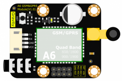
| Num | Label | Description |
|---|---|---|
| 1 | TX | TX (2.8V HIgh Level) |
| 2 | RX | RX |
| 3 | GND | GND |
| 4 | VCC | Power + (5V) |
Arduino GSM & GPRS Tutorial
In this tutorial, we'll use Arduino UNO Software Serial Port to connect A6 GSM & GPRS module
Requirements
-
Hardware
- DFRduino UNO R3 (or similar) x 1
- Gravity: UART A6 GSM & GPRS Module x1
- 3.5mm earphone with MIC
- M-M/F-M/F-F Jumper wires
-
Software
- Arduino IDE, Click to Download Arduino IDE from Arduino®
Connection Diagram
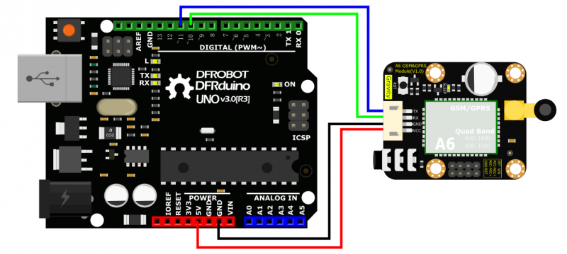
- TX-Pin10, RX-Pin11
- Please plug the earphone in the earphone jack, if you want to make a phone call.
GSM initialization
- GSM Initialization
#include <SoftwareSerial.h>
SoftwareSerial mySerial(11, 10);  // TX-Pin11, RX-Pin10
void updateSerial()
{
  delay(2000);
  while (Serial.available()) {
    mySerial.write(Serial.read());//Forward what Serial received to Software Serial Port
  }
  while(mySerial.available()) {
    Serial.write(mySerial.read());//Forward what Software Serial received to Serial Port
  }

}

void setup()
{
  Serial.begin(9600);
  mySerial.begin(9600);
}

void loop()
{
  mySerial.println("AT");          //Once the handshake test is successful, it will back to OK
  updateSerial();

  mySerial.println("AT+CSQ");      //Signal quality test, value range is 0-31, 31 is the best
  updateSerial();

  mySerial.println("AT+CCID");    //Read SIM information to confirm whether the SIM is plugged
  updateSerial();

  mySerial.println("AT+CREG?");    //Check whether it has registered in the network
  updateSerial();

  mySerial.println("AT+SNFS=0");  //Adjust to earphone mode(AT+SNFS=1 is microphone mode)
  updateSerial();

  mySerial.println("AT+CRSL=2");  //Adjust volume, volume range is 0-15, maximum:15
  updateSerial();

  while(1)
  {
    if(mySerial.available())
    {
      Serial.write(mySerial.read());   //Forward what Software Serial received to Serial Port
    if(Serial.available())
    {
      mySerial.write(Serial.read());  //Forward what Serial received to Software Serial Port
    }
  }
}
}
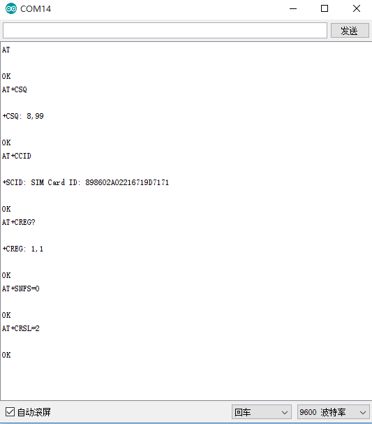
Make a Phone Call
- Make/answer a phone call by sending AT command in the Arduino serial interface. (Carriage Return; 9600bps)
- ATD+ phone number: Call the phone number
- e.g. ATD12345678
- Ring: A calling
- ATA: Answer
- ATH: Hang up
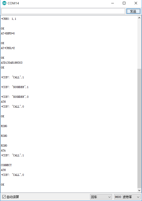
Send SMS
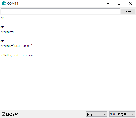
- Send SMS with Arduino UNO
#include <SoftwareSerial.h>
SoftwareSerial mySerial(11, 10);  // TX-Pin11, RX-Pin10
void updateSerial()
{
  delay(2000);
  while (Serial.available()) {
    mySerial.write(Serial.read());//Data received by Serial will be outputted by mySerial }
  while(mySerial.available()) {
    Serial.write(mySerial.read());//Data received by mySerial will be outputted by Serial }

}

void setup()
{
  Serial.begin(9600);
  mySerial.begin(9600);
}

void loop()
{
  mySerial.println("AT");          // Once the handshake test is successful, it will back to OK

  updateSerial();
  mySerial.println("AT+CMGF=1");   // Configuring mode is TEST, only English texts are available
  updateSerial();
  mySerial.println("AT+CMGS=\"xxxxxxxxxxx\"");//xxxxxxxxxxx is the phone number
  updateSerial();
  mySerial.print("Hello, this is a test"); //text content
  updateSerial();
  mySerial.write(26);
  while(1)
  {
    if(mySerial.available())
    {
      Serial.write(mySerial.read());//Data received by mySerial will be outputted by Serial }
    if(Serial.available())
    {
      mySerial.write(Serial.read());//Data received by Serial will be outputted by mySerial }
  }
}
GPRS Application
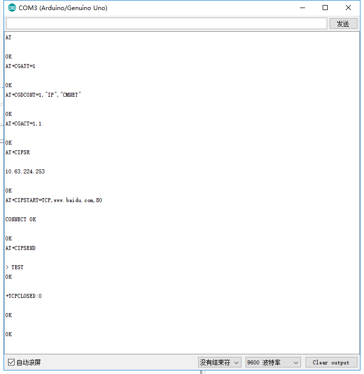
- Visit a web server
#include <SoftwareSerial.h>
SoftwareSerial mySerial(11, 10);  // TX-Pin11, RX-Pin10
void updateSerial()
{
  delay(2000);
  while (Serial.available()) {
    mySerial.write(Serial.read());//Data received by Serial will be outputted by mySerial
  }
  while(mySerial.available()) {
    Serial.write(mySerial.read());//Data received by mySerial will be outputted by Serial}
}

void setup()
{
  Serial.begin(9600);
  mySerial.begin(9600);
}

void loop()
{
  mySerial.println("AT");          // Once the handshake test is successful, it will back to OK
 updateSerial();
  mySerial.println("AT+CGATT=1 "); //The basic adhere network command of Internet connection
  updateSerial();
  mySerial.println("AT+CGDCONT=1,\"IP\",\"CMNET\"");//Set PDP parameter
  updateSerial();
  mySerial.println("AT+CGACT=1,1");//Activate PDP; Internet connection is available after successful PDP activation
  updateSerial();
  mySerial.println("AT+CIFSR");//Get local IP address
  updateSerial();
  mySerial.println("AT+CIPSTART=TCP,www.baidu.com,80");// Connect to the server then the server will send back former data
  updateSerial();
  updateSerial();
  delay(2000);
  updateSerial();
  mySerial.println("AT+CIPSEND");// Send data request to the server
  updateSerial();
  mySerial.print("TEST");// Send data to the server
  updateSerial();
  mySerial.write(26);// Terminator
  while(1)
    {
    if(mySerial.available())
    {
      Serial.write(mySerial.read());//Data received by mySerial will be outputted by Serial
    }
    if(Serial.available())
    {
      mySerial.write(Serial.read());//Data received by Serial will be outputted by mySerial
    }
  }
}
AT Commands
- In this section, we'll show you how to use AT Command to debug the GSM function.
Requirements
-
Hardware
- USB to TTL Converter (CP210) (or similar) x 1
- Gravity: UART A6 GSM & GPRS Module x1
- 3.5mm earphone with MIC
- M-M/F-M/F-F Jumper wires
-
Software
- Any Serial Assistant Software.You can use our Serial debugging assistant, Coolterm or DF Serial Debugger by Lisper.
Connection Diagram

- Please plug the earphone in the earphone jack, if you want to make a phone call.
GSM Initialization
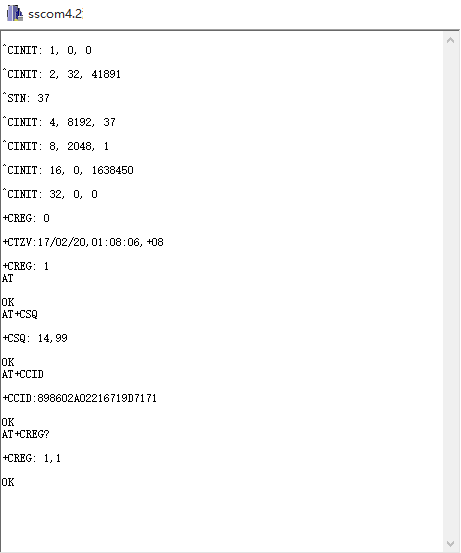
- The module will connect to the telecomm base station automatically and read data from the basement, it will output the GSM information via the Serial port, when you connect it to PC.
- Check the module initializationsState with 3 commands
- AT + CCID: to check SIM and CCID of SIM
- e.g. AT+CCID +CCID:898602A02216719D7171
- AT + CSQ: Check signal quality
- e.g. AT+CSQ=? +CSQ: (0-31, 99), (0-7, 99) (31 is the best)
- AT + CREG? : Check Internet register stats
- e.g. AT+CREG? +CREG: 1,1 //Registered network, local mode
- AT + CCID: to check SIM and CCID of SIM
Make a Phone Call
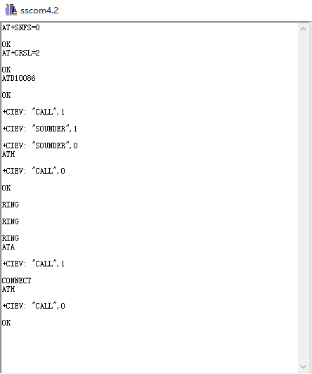
- Switch to earphone mode with 2 commands
- AT+ SNFS = 0: Switch to earphone mode (AT+SNFS=1 is microphone mode)
- AT + CRSL =2: Adjust volume (volume range is 0-15, maximum:15)
- Make/answer a phone call
- ATD+ phone number: Call the phone number
- e.g. ATD12345
- Ring: A calling
- ATA: Answer
- ATH: Hang up
- ATD+ phone number: Call the phone number
Send SMS
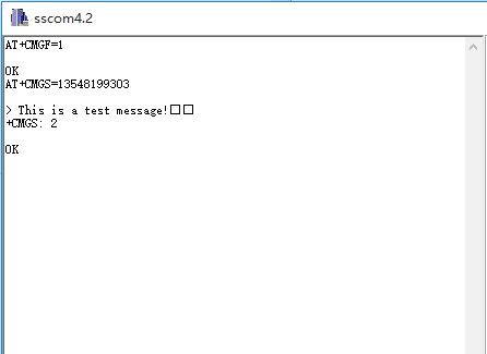
- TEXT Mode
- AT+CMGF=1: Config TEXT mode, only English texts are available
- AT+CMGS=13548199303: Configuring the receiving object
- It will display input indicator ">", and now you can enter the your SMS content, end with 0X1A or you can use "Ctrl+Z" to send SMS. It should return: OK
GPRS Application
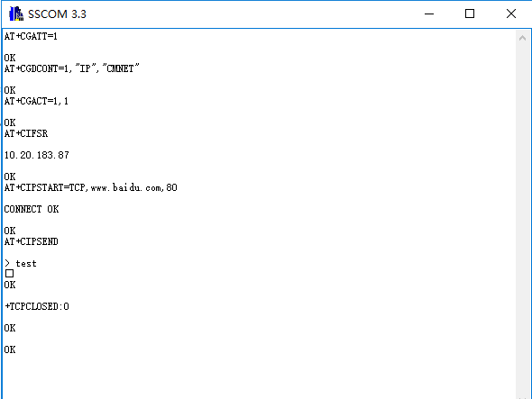
- AT+CGATT=1: The basic adhere network command of Internet connection
- AT+CGDCONT=1,"IP","CMNET": Set PDP parameter
- AT+CGACT=1: Activate PDP; Internet connection is available after successful PDP activation
- AT+CIFSR: Get local IP address
- AT+CIPSTART=TCP,www.baidu.com,80: Connect to the server then the server will send back former data
- AT+CIPSEND: Send data request to the server, input command and indicator “>” shows, input content and end with 0X1A or input Ctrl+Z, return OK then send the text.
- AT+CIPCLOSE: Disconnect the connection
FAQ
| For any questions, advice or cool ideas to share, please visit the DFRobot Forum. |
|---|
