Introduction
How to describe the tilt using data from an accelerometer? We have many products about Accelerometer like ADXL345, BMA220, 10-Axis Accelerometer etc., they could offer the raw data, but how to deal with it?
This page will talk about some basic notes for these sensors and two methods, which are Yaw-Pitch-Roll and Tilt Angle respectively, for tilt calculation.
Basic knowledge
1. Accelerometer sensors measure the difference between any linear acceleration in the accelerometer’s reference frame and the earth's gravitational field vector.
2. In the absence of linear acceleration, the accelerometer output is a measurement of the rotated gravitational field vector and can be used to determine the accelerometer pitch and roll orientation angles.
3. The orientation angles are dependent on the order in which the rotations are applied. The most common order is the aerospace sequence of yaw then pitch and finally a roll rotation.
4. Accelerometer sensors are insensitive to rotation about the earth's gravitational field vector. The equations for the roll and pitch angles therefore have mathematical instabilities when rotation axes happen to become aligned with gravity and point upwards or downwards. A workaround is presented to prevent this instability occurring.
5. Simple vector algebra expressions are derived for computing the tilt of the accelerometer from vertical or the rotation angle between any two accelerometer readings.
6. The most common application of accelerometers in consumer electronics is switching between portrait or landscape display modes. An algorithm is presented for controlling a tablet PC’s display orientation.
Yaw-Pitch-Roll
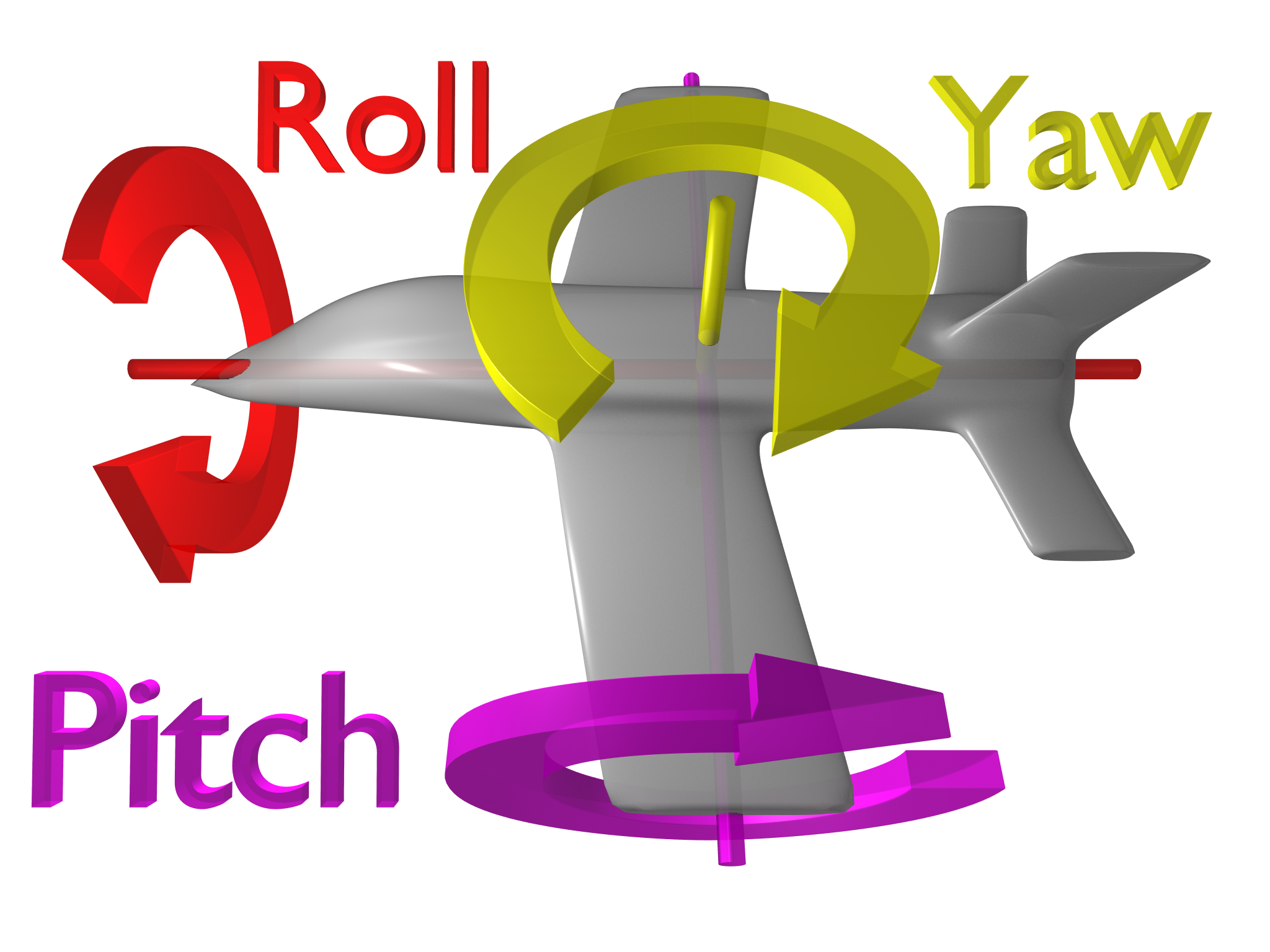
Let's take a look at what's the Yaw-Pitch-Roll(ψ-θ-φ). 
There are totally six suquences for any physical rotation:
- R-xyz
- R-yxz
- R-zxy
- R-zyx
- R-xzy
- R-yzx
Different rotation suquence may result in the same posture, or saying that the same posture have different pitch and roll, that is why we have to define a default sequence: Yaw-Pitch-Roll(ψ-θ-φ).
image:roll.gif|X - Roll - φ image:picth.gif|Y - Pitch - θ image:yaw.gif|Z - Yaw - ψ
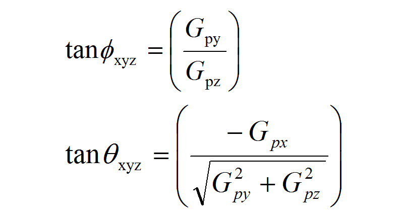
And the estimation of R-xyz is (From Freescale): 
Tilt Angle
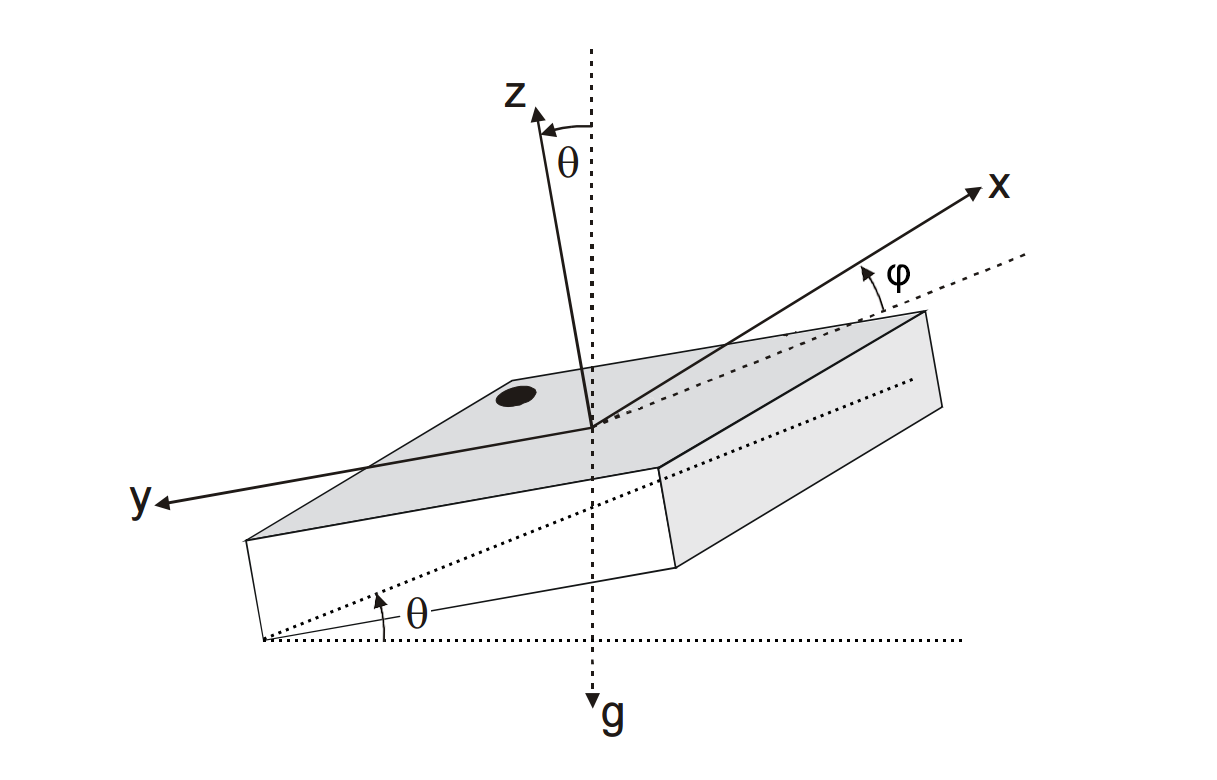
We have already studied the Yaw-Pitch-Roll angle, they could tell how to rotate an object by its X - Y axis to a specified posture. Actually, there is another method to expree the exact spatial position, that is Tilt angle showing in the picture below. How to understand the relationship between them? You may came to think the Cartesian coordinates and Polar coordinates, that's it.

And the estimation of the angles is (From Bosch Sensortec):
acc_x = 1g * sinθ * cosφ <br>
acc_y = - 1g * sinθ * sinφ <br>
acc_z = 1g * cosθ <br>
→ acc_y/acc_x = - tanφ
Sample Sketch
This is a part of Roll-Pitch calculation sketch for DFRobot ADXL345. You could add this sub-function to your 3-axis Accelerometer sketch.
int x, y, z;                        //three axis acceleration data
double roll = 0.00, pitch = 0.00;       //Roll & Pitch are the angles which rotate by the axis X and y

void RP_calculate(){
  double x_Buff = float(x);
  double y_Buff = float(y);
  double z_Buff = float(z);
  roll = atan2(y_Buff , z_Buff) * 57.3;
  pitch = atan2((- x_Buff) , sqrt(y_Buff * y_Buff + z_Buff * z_Buff)) * 57.3;
}
Click links below to visit ADXL345 wiki page.
English version / 中文版
More
BMA 220 DataSheet
Tilt Sensing Using a Three-Axis Accelerometer
Arduino IMU: Pitch & Roll from an Accelerometer
 Go Shopping Triple Axis Accelerometer BMA220 (Tiny) SKU:SEN0168
Category: DFRobot > Sensors &Modules > Sensors > IMU Sensors