Introduction
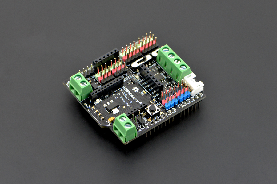
The new IO Expansion Shield V7 has arrived, and comes the best selling family of IO expansion shield for Arduino. For the past few years these expansion shields have been aiding thousands of makers to create,to expand, to share their sparkles of idea and ingenuity, and now comes the young V7.
The new IO Expansion Shield V7 not only inherits it's predecessors advantages, but also enjoys numerous new features:
- Compatible with the new Arduino Due
- Support 3.3V/5V operating voltage
- Switch for wireless communtcation & programme
- More easily recognizable interfaces
- Colorful header for illustrating digital or analog pins
- Immersion gold surface
Features
- Extend ports to 3Pins, convenient to plugin 3P modules
- Digital Pins x 14 (contains 6 PWM pins)
- Analog Pins x 6
- Rich communication and enclosure interfaces
- Xbee Bluetooth, WIFI, and Xbee communication modules can be directly plugged into the central
- Extended interfaces for normal Bluetooth modules, APC and SD cards
- External power extensions provide a lasting battery life for your Arduino works
- The external 5.5V power supply provides 3.3V regulated power supply and is compatible with 3.3V components
- Compatible with a variety of module interfaces, making it easy to plug in some wireless communication modules and two I2C interfaces.
PinOut

Introduction for Digital pins
- RX:D0
- TX:D1
- SPI interface SS:D4
- SPI interface MOSI:D11
- SPI interface MISO:D12
- SPI interface SCK:D13
LED: there is an onboard LED, please connect the LED to Digital pin 13 (D13).
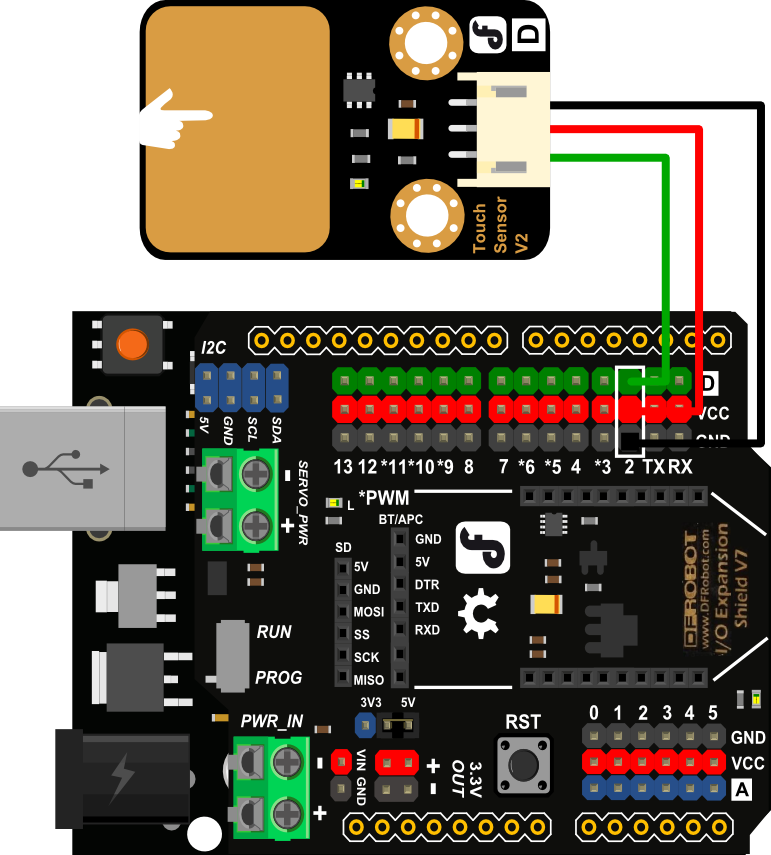
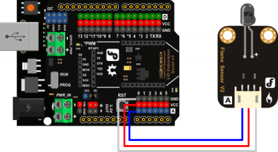
D&A: new version IO expansion shield printed with "D" and "A".
"D": Represents a digital signal. That is, connect to the digital pins of mainboard.
"A": Represents an analog signal. That is, connect to the analog pins of mainboard.
Compared with limited power-supply interfaces in mainly mainboards, IO Expansion Shield increase a large amount of power-supply interfaces and GND pins. Therefore, users no need to worry about the shortage of pwer supply interfaces when connecting many modules.
Special description of the color distinction in DF:
| Color | Function |
|---|---|
| Green | Digital Signal |
| Blue | Analog Signal |
| Red | VCC(+) |
| Black | GND(-) |
User Guide
-
Switch to RUN/PROG
The new extension board adds a switch to Run and Download the program. When you download the code, please dial it to "PROG". When running, dial it to the "RUN".
Users who have used V5 may know that when using XEee these communication modules, because of serial usage conflicts, we need to unplug the communication module to download the code. While in the 7.0 version, we just need to dial the switch. -
Switch to output 3.3V/5V
The jumper cap can be used to select whether the output power supply is 5V or 3.3V. It is easy to power sensors that require a 3.3V power supply. If there is no jumper cap, the VCC pin output voltage is 0. -
Stable 3.3V Output
This power output is different from the output voltage of other VCC pins. Other VCC pins are related to the previous power jumper cap selection, but this is not, it is a constant 3.3V output voltage. -
External Input Power Supply(6V to 12V)
An external input power supply interface is provided, and the figure above shows that there are two interfaces to choose from, but the input voltage should be controlled within 6V to 12V. -
Servo Input Power Supply(5V to 12V)
The digital pins can be connected to an external power supply within 5V to 12V.
Two Available Situations
1.There are device connected to digital pins, such as in some robot platforms that use multiple servos, resulting in a situation where the current is too low to work properly. In this case, the current can be replenished by a 5V external power supply.
2.When the digital pin is connected to a device that requires a larger power supply, it can be connected directly to a 5 to 12V extenal power supply in this interface.
Applications
- Applied to digital sensor

- Applied to analog sensor

- Applied to wireless connection module

FAQ
| Q&A | Some general Arduino Problems/FAQ/Tips |
|---|---|
| Q | I inserted an xbee module on the expansion board, then switched the extension board to Prog, but it still failed to upload, how to solve it? |
| A | It may be that the power of xbee module is too high, usb power supply cannot offer enough power. You can try to add a lithium battery power supply to the mainboard. |
| Q | Once the sensor is plugged into the expansion shield, the sensor would not work properly. Why there is no voltage in expansion shield VCC? |
| A | Please check whether the jumper cap at the 3.3V voltage switch is dropped. You can connect it with jumper wire. |
| A | For any questions, advice or cool ideas to share, please visit the DFRobot Forum. |
More Documentation
-
Old Version
-
Documents*
| Schematic Note: The lables on the shield are different within the schematic more or less, but you can pay attention to these items to help you understand it better: SERVO_PWR - PWR_VIN or PWR_IN - Vin |
|---|
