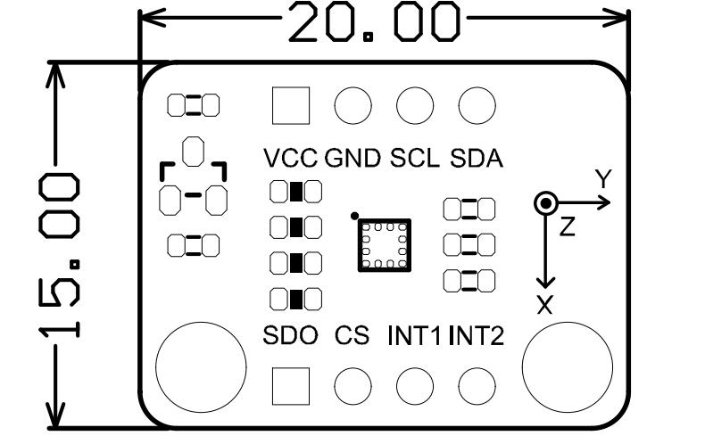
LIS2DW12_Triple_Axis_Accelerometer_SKU_SEN0405-DFRobot

Introduction

The LIS2DW12 is an ultra-low power three-axis linear accelerometer with two independent programmable interrupts and a dedicated internal engine that can achieve various motion and acceleration detection including free-fall, portrait/landscape detection, 6D/4D orientation detection, configurable single/double-tap recognition, stationary/motion detection, motion wakeup for smart power saving, etc. And for your convenience, we provide you with sample programs for the above functions. The LIS2DW12 has user-selectable full scales of ±2g/±4g/±8g/±16g and is capable of measuring acceleration with output data rates from 1.6Hz to 1600Hz. Besides that, it offers multiple operating modes with multiple bandwidths, allowing you to choose freely based on your needs.

Features

Specification

Application

Board Overview

三轴加速度计 三轴加速度计

No. Silkscreen Description
1 VCC 5V/3V3
2 GND GND
3 SCL I2C Clock Line/SPI Clock Line
4 SDA I2C Data Line/SPI Data Line
5 INT2 Interrupt Pin 2
6 INT1 Interrupt Pin 1
7 CS SPI chip-select line
8 SDO I2C Address select pin/SPI data line MOSI

Note:

Connections for different communication methods:

1

2

3

Mainboard Default connected pin
UNO/MEGA2560 D2
Leonardo D3
Micro:bit P0
ESP32/ESP8266/ARDUINO_SAM_ZERO D6
Raspberry Pi GPIO25

Tutorial for M0

Connect your sensor to M0 controller.

Requirements

Connection

   DFRobot_LIS();
  /**
   * @brief Initialize the function
   * @return true(Succeed)/false(Failed)
   */
  bool begin(void);

  /**
   * @brief Get chip id
   * @return 8 bit serial number
   */
  uint8_t getID();

  /**
   * @brief Enable interrupt
   * @param source Interrupt pin selection
              eINT1 = 0,/<int1 >/
              eINT2,/<int2>/
   * @param event Interrupt event selection
                   eXLowerThanTh ,/<The acceleration in the x direction is less than the threshold>/
                   eXHigherThanTh ,/<The acceleration in the x direction is greater than the threshold>/
                   eYLowerThanTh,/<The acceleration in the y direction is less than the threshold>/
                   eYHigherThanTh,/<The acceleration in the y direction is greater than the threshold>/
                   eZLowerThanTh,/<The acceleration in the z direction is less than the threshold>/
                   eZHigherThanTh,/<The acceleration in the z direction is greater than the threshold>/
   */
  void enableInterruptEvent(eInterruptSource_t source, eInterruptEvent_t event);

  /**
   * @brief Set measurement range
   * @param range Range(g)
                  eH3lis200dl_100g, //±100g
                  eH3lis200dl_200g, //±200g

                  eLis331hh_6g = 6,//±6g
                  eLis331hh_12g = 12 //±12g
                  eLis331hh_24g = 24 //±24g  
    @return true(Set successfully)/false(Set failed)
   */
  bool setRange(eRange_t range);

  /**
   * @brief Set data measurement rate
   * @param rate rate(HZ)
                  ePowerDown_0HZ   //Measurement off
                  eLowPower_halfHZ //0.5 hz
                  eLowPower_1HZ
                  eLowPower_2HZ
                  eLowPower_5HZ
                  eLowPower_10HZ
                  eNormal_50HZ
                  eNormal_100HZ
                  eNormal_400HZ
                  eNormal_1000HZ
   */
  void setAcquireRate(ePowerMode_t rate);

  /**
   * @brief Set data filtering mode
   * @param mode Four modes
                 eCutOffMode1 = 0,
                 eCutOffMode2,
                 eCutOffMode3,
                 eCutOffMode4,
                 eShutDown, no filering
     eg: Select eCutOffMode1 in 50HZ, and the filtered frequency is 1HZ
   *|---------------------------High-pass filter cut-off frequency configuration-----------------------------|
   *|--------------------------------------------------------------------------------------------------------|
   *|                |    ft [Hz]      |        ft [Hz]       |       ft [Hz]        |        ft [Hz]        |
   *|   mode         |Data rate = 50 Hz|   Data rate = 100 Hz |  Data rate = 400 Hz  |   Data rate = 1000 Hz |
   *|--------------------------------------------------------------------------------------------------------|
   *|  eCutOffMode1  |     1           |         2            |            8         |             20        |
   *|--------------------------------------------------------------------------------------------------------|
   *|  eCutOffMode2  |    0.5          |         1            |            4         |             10        |
   *|--------------------------------------------------------------------------------------------------------|
   *|  eCutOffMode3  |    0.25         |         0.5          |            2         |             5         |
   *|--------------------------------------------------------------------------------------------------------|
   *|  eCutOffMode4  |    0.125        |         0.25         |            1         |             2.5       |
   *|--------------------------------------------------------------------------------------------------------|
   */
  void setHFilterMode(eHighPassFilter_t mode);

  /**
   * @brief Set the threshold of interrupt source 1 interrupt
   * @param threshold The threshold we set before is within measurement range(unit:g)
   */
  void setInt1Th(uint8_t threshold);

  /**
   * @brief Set interrupt source 2 interrupt generation threshold
   * @param threshold The threshold we set before is within measurement range(unit:g)
   */
  void setInt2Th(uint8_t threshold);

  /**
   * @brief Enable sleep wake function
   * @param enable true(enable)\false(disable)
   * @return false Indicate enable failed/true Indicate enable successful
   */
  bool enableSleep(bool enable);

  /**
   * @brief Check whether the interrupt event'event' is generated in interrupt 1
   * @param event Interrupt event
                   eXLowerThanTh ,/<The acceleration in the x direction is less than the threshold>/
                   eXHigherThanTh ,/<The acceleration in the x direction is greater than the threshold>/
                   eYLowerThanTh,/<The acceleration in the y direction is less than the threshold>/
                   eYHigherThanTh,/<The acceleration in the y direction is greater than the threshold>/
                   eZLowerThanTh,/<The acceleration in the z direction is less than the threshold>/
                   eZHigherThanTh,/<The acceleration in the z direction is greater than the threshold>/
   * @return true This event generated
             false This event not generated
   */
  bool getInt1Event(eInterruptEvent_t event);

  /**
   * @brief Check whether the interrupt event'event' is generated in interrupt 2
   * @param event Interrupt event
                   eXLowerThanTh ,/<The acceleration in the x direction is less than the threshold>/
                   eXHigherThanTh ,/<The acceleration in the x direction is greater than the threshold>/
                   eYLowerThanTh,/<The acceleration in the y direction is less than the threshold>/
                   eYHigherThanTh,/<The acceleration in the y direction is greater than the threshold>/
                   eZLowerThanTh,/<The acceleration in the z direction is less than the threshold>/
                   eZHigherThanTh,/<The acceleration in the z direction is greater than the threshold>/
   * @return true This event generated
             false This event not generated
   */
  bool getInt2Event(eInterruptEvent_t event);

  /**
   * @brief Get the acceleration in the x direction
   * @return acceleration from x 
   */
  int32_t readAccX();

  /**
   * @brief Get the acceleration in the y direction
   * @return acceleration from y
   */
  int32_t readAccY();

  /**
   * @brief Get the acceleration in the z direction
   * @return acceleration from z
   */
  int32_t readAccZ();

  /**
   * @brief Get the acceleration in the three directions of xyz
   * @param accx Store the variable of acceleration in x direction
   * @param accy Store the variable of acceleration in y direction
   * @param accz Store the variable of acceleration in z direction
   * @return true(Get data successfully/false(Data not ready)
   */
  bool getAcceFromXYZ(int32_t &accx,int32_t &accy,int32_t &accz);

  /**
   * @brief Get whether the sensor is in sleep mode
   * @return true(In sleep mode)/false(In normal mode)
   */
  bool getSleepState();

  /**
   * @brief Set the sleep state flag
   * @param into true(Flag the current mode as sleep mode)
                 false(Flag the current mode as normal mode)
   */
  void setSleepFlag(bool into);

Sample code 1-Read acceleration of x, y and z(getAcceleration.ino)

Sample Code 1

/**!
 * @file getAcceleration.ino
 * @brief Get the acceleration in the three directions of xyz, the range can be ±2g, ±4g, ±8g or ±16g, set by the setRange() function
 * @n In this example, the continuous measurement mode is selected by default -- the acceleration data will be measured continuously according to the measuring rate.
 * @n You can also use the single data conversion on demand mode 1. You need to select a suitable conversion mode in the setPowerMode() function
 * @n                                                            2. Fill in the setDataRate() function with the eSetSwTrig parameter
 * @n                                                            3. Request a measurement by the demandData() function
 * @n When using SPI, chip select pin can be modified by changing the value of LIS2DW12_CS
 * @copyright  Copyright (c) 2010 DFRobot Co.Ltd (http://www.dfrobot.com)
 * @licence     The MIT License (MIT)
 * @author [fengli](li.feng@dfrobot.com)
 * @version  V1.0
 * @date  2021-01-16
 * @get from https://www.dfrobot.com
 * @https://github.com/DFRobot/DFRobot_LIS
 */


#include <DFRobot_LIS2DW12.h>
//When using I2C communication, use the following program to construct an object by DFRobot_LIS2DW12_I2C
/*!
 * @brief Constructor 
 * @param pWire I2c controller
 * @param addr  I2C address(0x18/0x19)
 */
//DFRobot_LIS2DW12_I2C acce(&Wire,0x18);
DFRobot_LIS2DW12_I2C acce;


//When using SPI communication, use the following program to construct an object by DFRobot_LIS2DW12_SPI
#if defined(ESP32) || defined(ESP8266)
#define LIS2DW12_CS  D3
#elif defined(__AVR__) || defined(ARDUINO_SAM_ZERO)
#define LIS2DW12_CS 3
#elif (defined NRF5)
#define LIS2DW12_CS 2  //The pin on the development board with the corresponding silkscreen printed as P2
#endif
/*!
 * @brief Constructor 
 * @param cs Chip selection pinChip selection pin
 * @param spi SPI controller
 */
//DFRobot_LIS2DW12_SPI acce(/*cs = */LIS2DW12_CS,&SPI);
//DFRobot_LIS2DW12_SPI acce(/*cs = */LIS2DW12_CS);

void setup(void){

  Serial.begin(9600);
  while(!acce.begin()){
     Serial.println("Communication failed, check the connection and I2C address setting when using I2C communication.");
     delay(1000);
  }
  Serial.print("chip id : ");
  Serial.println(acce.getID(),HEX);
  //Chip soft reset
  acce.softReset();
  //Set whether to collect data continuously
  acce.continRefresh(true);


  /**!
    Set the sensor data collection rate:
               eRate_0hz           /<Measurement off>/
               eRate_1hz6          /<1.6hz, use only under low-power mode>/
               eRate_12hz5         /<12.5hz>/
               eRate_25hz          
               eRate_50hz          
               eRate_100hz         
               eRate_200hz         
               eRate_400hz       /<Use only under High-Performance mode>/
               eRate_800hz       /<Use only under High-Performance mode>/
               eRate_1k6hz       /<Use only under High-Performance mode>/
               eSetSwTrig        /<The software triggers a single measurement>/
  */
  acce.setDataRate(DFRobot_LIS2DW12::eRate_50hz);

  /**!
    Set the sensor measurement range:
                   e2_g   /<±2g>/
                   e4_g   /<±4g>/
                   e8_g   /<±8g>/
                   e16_g  /< ±16g>/
  */
  acce.setRange(DFRobot_LIS2DW12::e2_g);


  /**!
    Filter settings:
           eLPF (Low pass filter)
           eHPF (High pass filter)
  */
  acce.setFilterPath(DFRobot_LIS2DW12::eLPF);

  /**!
    Set bandwidth:
        eRateDiv_2  /<Rate/2 (up to Rate = 800 Hz, 400 Hz when Rate = 1600 Hz)>/
        eRateDiv_4  /<Rate/4 (High Power/Low power)>*
        eRateDiv_10 /<Rate/10 (HP/LP)>/
        eRateDiv_20 /< Rate/20 (HP/LP)>/
  */
  acce.setFilterBandwidth(DFRobot_LIS2DW12::eRateDiv_4);

  /**!
   Set power mode:
       eHighPerformance_14bit         /<High-Performance Mode,14-bit resolution>/
       eContLowPwr4_14bit             /<Continuous measurement,Low-Power Mode 4(14-bit resolution)>/
       eContLowPwr3_14bit             /<Continuous measurement,Low-Power Mode 3(14-bit resolution)>/
       eContLowPwr2_14bit             /<Continuous measurement,Low-Power Mode 2(14-bit resolution)/
       eContLowPwr1_12bit             /<Continuous measurement,Low-Power Mode 1(12-bit resolution)>/
       eSingleLowPwr4_14bit           /<Single data conversion on demand mode,Low-Power Mode 4(14-bit resolution)>/
       eSingleLowPwr3_14bit           /<Single data conversion on demand mode,Low-Power Mode 3(14-bit resolution)>/
       eSingleLowPwr2_14bit           /<Single data conversion on demand mode,Low-Power Mode 2(14-bit resolution)>/
       eSingleLowPwr1_12bit           /<Single data conversion on demand mode,Low-Power Mode 1(12-bit resolution)>/
       eHighPerformanceLowNoise_14bit /<High-Performance Mode,Low-noise enabled,14-bit resolution>/
       eContLowPwrLowNoise4_14bit     /<Continuous measurement,Low-Power Mode 4(14-bit resolution,Low-noise enabled)>/
       eContLowPwrLowNoise3_14bit     /<Continuous measurement,Low-Power Mode 3(14-bit resolution,Low-noise enabled)>/
       eContLowPwrLowNoise2_14bit     /<Continuous measurement,Low-Power Mode 2(14-bit resolution,Low-noise enabled)>/
       eContLowPwrLowNoise1_12bit     /<Continuous measurement,Low-Power Mode 1(12-bit resolution,Low-noise enabled)>/
       eSingleLowPwrLowNoise4_14bit   /<Single data conversion on demand mode,Low-Power Mode 4(14-bit resolution),Low-noise enabled>/
       eSingleLowPwrLowNoise3_14bit   /<Single data conversion on demand mode,Low-Power Mode 3(14-bit resolution),Low-noise enabled>/
       eSingleLowPwrLowNoise2_14bit   /<Single data conversion on demand mode,Low-Power Mode 2(14-bit resolution),Low-noise enabled>/
       eSingleLowPwrLowNoise1_12bit   /<Single data conversion on demand mode,Low-Power Mode 1(12-bit resolution),Low-noise enabled>/
  */
  acce.setPowerMode(DFRobot_LIS2DW12::eContLowPwrLowNoise2_14bit);
  Serial.print("Acceleration:\n");
  delay(100);
}

void loop(void){
    //Request a measurement under single data conversion on demand mode
    //acce.demandData();
    //The mearsurement range is ±2g,±4g,±8g or ±16g, set by the setRange() function.
    Serial.print("x: ");
    //Read the acceleration in the x direction
    Serial.print(acce.readAccX());
    Serial.print(" mg \ty: ");
    //Read the acceleration in the y direction
    Serial.print(acce.readAccY());
    Serial.print(" mg \tz: ");
    //Read the acceleration in the z direction
    Serial.print(acce.readAccZ());
    Serial.println(" mg");
    delay(300);
}

Result

Result 1

Sample code 2-Wakeup function(wakeUp.ino)

Sample Code 2

/**!
 * @file wakeUp.ino
 * @brief When the acceleration change in x, y or z direction is detected to exceed the threshold we set before, the chip will generate a wake-up event.
 * @n By accessing the chip register, we can know which direction of movement wakes up the chip.
 * @n In this example, it is necessary to set the wake-up duration by setWakeUpDur().
 * @n When woken up, the chip will last for a while before it enters the sleep state.
 * @n And to set the threshold by setWakeUpThreshold(). When the acceleration change exceeds this value, the eWakeUp event will be triggered.
 * @n When using SPI, chip select pin can be modified by changing the value of LIS2DW12_CS
 * @copyright  Copyright (c) 2010 DFRobot Co.Ltd (http://www.dfrobot.com)
 * @licence     The MIT License (MIT)
 * @author [fengli](li.feng@dfrobot.com)
 * @version  V1.0
 * @date  2021-01-16
 * @get from https://www.dfrobot.com
 * @https://github.com/DFRobot/DFRobot_LIS
 */

#include <DFRobot_LIS2DW12.h>

//When using I2C communication, use the following program to construct an object by DFRobot_LIS2DW12_I2C
/*!
 * @brief Constructor 
 * @param pWire I2c controller
 * @param addr  I2C address(0x18/0x19)
 */
//DFRobot_LIS2DW12_I2C acce(&Wire,0x18);
DFRobot_LIS2DW12_I2C acce;

//When using SPI communication, use the following program to construct an object by DFRobot_LIS2DW12_SPI
#if defined(ESP32) || defined(ESP8266)
#define LIS2DW12_CS  D3
#elif defined(__AVR__) || defined(ARDUINO_SAM_ZERO)
#define LIS2DW12_CS  3
#elif (defined NRF5)
#define LIS2DW12_CS  2  //The pin on the development board with the corresponding silkscreen printed as P2
#endif
/*!
 * @brief Constructor 
 * @param cs  Chip selection pinChip selection pin
 * @param spi SPI controller
 */
//DFRobot_LIS2DW12_SPI acce(/*cs = */LIS2DW12_CS,&SPI);
//DFRobot_LIS2DW12_SPI acce(/*cs = */LIS2DW12_CS);

void setup(void){
  Serial.begin(9600);
  while(!acce.begin()){
     Serial.println("Communication failed, check the connection and I2C address setting when using I2C communication.");
     delay(1000);
  }
  Serial.print("chip id : ");
  Serial.println(acce.getID(),HEX);
  //Chip soft reset
  acce.softReset();

  /**!
    Set the sensor measurement range:
                   e2_g   /<±2g>/
                   e4_g   /<±4g>/
                   e8_g   /<±8g>/
                   e16_g  /< ±16g>/
  */
  acce.setRange(DFRobot_LIS2DW12::e2_g);

  /**!
   Set power mode:
       eHighPerformance_14bit         /<High-Performance Mode,14-bit resolution>/
       eContLowPwr4_14bit             /<Continuous measurement,Low-Power Mode 4(14-bit resolution)>/
       eContLowPwr3_14bit             /<Continuous measurement,Low-Power Mode 3(14-bit resolution)>/
       eContLowPwr2_14bit             /<Continuous measurement,Low-Power Mode 2(14-bit resolution)/
       eContLowPwr1_12bit             /<Continuous measurement,Low-Power Mode 1(12-bit resolution)>/
       eSingleLowPwr4_14bit           /<Single data conversion on demand mode,Low-Power Mode 4(14-bit resolution)>/
       eSingleLowPwr3_14bit           /<Single data conversion on demand mode,Low-Power Mode 3(14-bit resolution)>/
       eSingleLowPwr2_14bit           /<Single data conversion on demand mode,Low-Power Mode 2(14-bit resolution)>/
       eSingleLowPwr1_12bit           /<Single data conversion on demand mode,Low-Power Mode 1(12-bit resolution)>/
       eHighPerformanceLowNoise_14bit /<High-Performance Mode,Low-noise enabled,14-bit resolution>/
       eContLowPwrLowNoise4_14bit     /<Continuous measurement,Low-Power Mode 4(14-bit resolution,Low-noise enabled)>/
       eContLowPwrLowNoise3_14bit     /<Continuous measurement,Low-Power Mode 3(14-bit resolution,Low-noise enabled)>/
       eContLowPwrLowNoise2_14bit     /<Continuous measurement,Low-Power Mode 2(14-bit resolution,Low-noise enabled)>/
       eContLowPwrLowNoise1_12bit     /<Continuous measurement,Low-Power Mode 1(12-bit resolution,Low-noise enabled)>/
       eSingleLowPwrLowNoise4_14bit   /<Single data conversion on demand mode,Low-Power Mode 4(14-bit resolution),Low-noise enabled>/
       eSingleLowPwrLowNoise3_14bit   /<Single data conversion on demand mode,Low-Power Mode 3(14-bit resolution),Low-noise enabled>/
       eSingleLowPwrLowNoise2_14bit   /<Single data conversion on demand mode,Low-Power Mode 2(14-bit resolution),Low-noise enabled>/
       eSingleLowPwrLowNoise1_12bit   /<Single data conversion on demand mode,Low-Power Mode 1(12-bit resolution),Low-noise enabled>/
  */
  acce.setPowerMode(DFRobot_LIS2DW12::eContLowPwrLowNoise1_12bit);

  /**!
    Set the sensor data collection rate:
               eRate_0hz           /<Measurement off>/
               eRate_1hz6          /<1.6hz, use only under low-power mode>/
               eRate_12hz5         /<12.5hz>/
               eRate_25hz          
               eRate_50hz          
               eRate_100hz         
               eRate_200hz         
               eRate_400hz       /<Use only under High-Performance mode>/
               eRate_800hz       /<Use only under High-Performance mode>/
               eRate_1k6hz       /<Use only under High-Performance mode>/
               eSetSwTrig        /<The software triggers a single measurement>/
  */
  acce.setDataRate(DFRobot_LIS2DW12::eRate_200hz);

  /**!
    Filter settings:
           eLPF(Low pass filter)
           eHPF(High pass filter)
  */
  acce.setFilterPath(DFRobot_LIS2DW12::eLPF);

  /**
    The wake-up duration – when woken up, the chip will last for a while before it enters the sleep state.
    dur (0 ~ 3)
    time = dur * (1/Rate)(unit:s)
    |                      An example of a linear relationship between an argument and time                                  |
    |------------------------------------------------------------------------------------------------------------------------|
    |                |                     |                          |                          |                           |
    |  Data rate     |       25 Hz         |         100 Hz           |          400 Hz          |         = 800 Hz          |
    |------------------------------------------------------------------------------------------------------------------------|
    |   time         |dur*(1s/25)= dur*40ms|  dur*(1s/100)= dur*10ms  |  dur*(1s/400)= dur*2.5ms |  dur*(1s/800)= dur*1.25ms |
    |------------------------------------------------------------------------------------------------------------------------|
   */
  acce.setWakeUpDur(/*dur =*/2);

  //Set wakeup threshold, when the acceleration change exceeds this value, the eWakeUp event will be triggered, unit:mg
  //The value is within the range
  acce.setWakeUpThreshold(/*threshold = */0.5);

  /**!
    Set the interrupt event of the int1 pin:
    eDoubleTap(Double click)
    eFreeFall(Free fall)
    eWakeUp(wake)
    eSingleTap(single-Click)
    e6D(Orientation change check)
  */
  acce.setInt1Event(DFRobot_LIS2DW12::eWakeUp);

  /**!
    Set the interrupt event of the int1 pin:
       eSleepChange = 0x40,/<Sleep change status routed to INT2 pad>/
       eSleepState  = 0x80,/<Enable routing of SLEEP_STATE on INT2 pad>/
  */
  //acce.setInt2Event(DFRobot_LIS2DW12::eSleepChange);
  delay(100);
}

void loop(void){

   //Wake-up event detected
   if(acce.actDetected()){
     Serial.print("wake-up event happened in ");
     //Wake-up motion direction detection
     DFRobot_LIS2DW12::eWakeUpDir_t dir  = acce.getWakeUpDir();
     if(dir == DFRobot_LIS2DW12::eDirX){
       Serial.println("x direction");
     }
     if(dir == DFRobot_LIS2DW12::eDirY){
       Serial.println("y direction");
     }
     if(dir == DFRobot_LIS2DW12::eDirZ){
       Serial.println("z direction");
     }
     delay(100);
   }
}

Result

Sample Code 2

Sample code 3-Tap detection(tap.ino)

Sample Code 3

/**!
 * @file tap.ino
 * @brief Single tap and double tap detection, tapping the module or the desktop near the module both can trigger the tap event
 * @n You can select to detect single tap or to detect both single tap and double tap by the setTapMode() function
 * @n When using SPI, chip select pin can be modified by changing the value of LIS2DW12_CS
 * @copyright  Copyright (c) 2010 DFRobot Co.Ltd (http://www.dfrobot.com)
 * @licence     The MIT License (MIT)
 * @author [fengli](li.feng@dfrobot.com)
 * @version  V1.0
 * @date  2021-01-16
 * @get from https://www.dfrobot.com
 * @https://github.com/DFRobot/DFRobot_LIS
 */


#include <DFRobot_LIS2DW12.h>


//When using I2C communication, use the following program to construct an object by DFRobot_LIS2DW12_I2C
/*!
 * @brief Constructor 
 * @param pWire I2c controller
 * @param addr  I2C address(0x18/0x19)
 */
//DFRobot_LIS2DW12_I2C acce(&Wire,0x18);
DFRobot_LIS2DW12_I2C acce;


//When using SPI communication, use the following program to construct an object by DFRobot_LIS2DW12_SPI
#if defined(ESP32) || defined(ESP8266)
#define LIS2DW12_CS  D3
#elif defined(__AVR__) || defined(ARDUINO_SAM_ZERO)
#define LIS2DW12_CS 3
#elif (defined NRF5)
#define LIS2DW12_CS 2  //The pin on the development board with the corresponding silkscreen printed as P2
#endif
/*!
 * @brief Constructor 
 * @param cs  Chip selection pinChip selection pin
 * @param spi SPI controller
 */
//DFRobot_LIS2DW12_SPI acce(/*cs = */LIS2DW12_CS,&SPI);
//DFRobot_LIS2DW12_SPI acce(/*cs = */LIS2DW12_CS);

void setup(void){
  Serial.begin(9600);
  while(!acce.begin()){
     Serial.println("Communication failed, check the connection and I2C address setting when using I2C communication.");
     delay(1000);
  }
  Serial.print("chip id : ");
  Serial.println(acce.getID(),HEX);
  //Chip soft reset
  acce.softReset();

  /**!
    Set the sensor measurement range:
                   e2_g   /<±2g>/
                   e4_g   /<±4g>/
                   e8_g   /<±8g>/
                   e16_g  /< ±16g>/
  */
  acce.setRange(DFRobot_LIS2DW12::e2_g);

  /**!
   Set power mode:
       eHighPerformance_14bit         /<High-Performance Mode,14-bit resolution>/
       eContLowPwr4_14bit             /<Continuous measurement,Low-Power Mode 4(14-bit resolution)>/
       eContLowPwr3_14bit             /<Continuous measurement,Low-Power Mode 3(14-bit resolution)>/
       eContLowPwr2_14bit             /<Continuous measurement,Low-Power Mode 2(14-bit resolution)/
       eContLowPwr1_12bit             /<Continuous measurement,Low-Power Mode 1(12-bit resolution)>/
       eSingleLowPwr4_14bit           /<Single data conversion on demand mode,Low-Power Mode 4(14-bit resolution)>/
       eSingleLowPwr3_14bit           /<Single data conversion on demand mode,Low-Power Mode 3(14-bit resolution)>/
       eSingleLowPwr2_14bit           /<Single data conversion on demand mode,Low-Power Mode 2(14-bit resolution)>/
       eSingleLowPwr1_12bit           /<Single data conversion on demand mode,Low-Power Mode 1(12-bit resolution)>/
       eHighPerformanceLowNoise_14bit /<High-Performance Mode,Low-noise enabled,14-bit resolution>/
       eContLowPwrLowNoise4_14bit     /<Continuous measurement,Low-Power Mode 4(14-bit resolution,Low-noise enabled)>/
       eContLowPwrLowNoise3_14bit     /<Continuous measurement,Low-Power Mode 3(14-bit resolution,Low-noise enabled)>/
       eContLowPwrLowNoise2_14bit     /<Continuous measurement,Low-Power Mode 2(14-bit resolution,Low-noise enabled)>/
       eContLowPwrLowNoise1_12bit     /<Continuous measurement,Low-Power Mode 1(12-bit resolution,Low-noise enabled)>/
       eSingleLowPwrLowNoise4_14bit   /<Single data conversion on demand mode,Low-Power Mode 4(14-bit resolution),Low-noise enabled>/
       eSingleLowPwrLowNoise3_14bit   /<Single data conversion on demand mode,Low-Power Mode 3(14-bit resolution),Low-noise enabled>/
       eSingleLowPwrLowNoise2_14bit   /<Single data conversion on demand mode,Low-Power Mode 2(14-bit resolution),Low-noise enabled>/
       eSingleLowPwrLowNoise1_12bit   /<Single data conversion on demand mode,Low-Power Mode 1(12-bit resolution),Low-noise enabled>/
  */
  acce.setPowerMode(DFRobot_LIS2DW12::eContLowPwrLowNoise1_12bit);

  /**!
    Set the sensor data collection rate:
               eRate_0hz           /<Measurement off>/
               eRate_1hz6          /<1.6hz, use only under low-power mode>/
               eRate_12hz5         /<12.5hz>/
               eRate_25hz          
               eRate_50hz          
               eRate_100hz         
               eRate_200hz         
               eRate_400hz       /<Use only under High-Performance mode>/
               eRate_800hz       /<Use only under High-Performance mode>/
               eRate_1k6hz       /<Use only under High-Performance mode>/
               eSetSwTrig        /<The software triggers a single measurement>/
  */
  acce.setDataRate(DFRobot_LIS2DW12::eRate_800hz);

  //Enable tap detection in the Z direction
  acce.enableTapDetectionOnZ(true);
  //Enable tap detection in Y direction
  acce.enableTapDetectionOnY(true);
  //Enable tap detection in the X direction
  acce.enableTapDetectionOnX(true);
  //The threshold setting in the X direction 
  //Threshold(mg),Can only be used in the range of ±2g
  acce.setTapThresholdOnX(/*Threshold = */0.5);
  //The threshold setting in the Y direction   //Threshold(mg),Can only be used in the range of ±2g
  acce.setTapThresholdOnY(/*Threshold = */0.5);
  //The threshold setting in the Z direction   //Threshold(mg),Can only be used in the range of ±2g)
  acce.setTapThresholdOnZ(/*Threshold = */0.5);


  /*
    Set the interval time between two taps when detecting double tap
    dur duration(0 ~ 15)
    time = dur * (1/ODR)(unit:s)
    |                                An example of a linear relationship between an argument and time                                               |
    |------------------------------------------------------------------------------------------------------------------------|
    |                |                     |                          |                          |                           |
    |  Data rate     |       25 Hz         |         100 Hz           |          400 Hz          |         = 800 Hz          |
    |------------------------------------------------------------------------------------------------------------------------|
    |   time         |dur*(1s/25)= dur*40ms|  dur*(1s/100)= dur*10ms  |  dur*(1s/400)= dur*2.5ms |  dur*(1s/800)= dur*1.25ms |
    |------------------------------------------------------------------------------------------------------------------------|
  */
  acce.setTapDur(/*dur=*/6);

  /**!
    Set tap detection mode:
       eOnlySingle(Single tap)
       eBothSingleDouble(Single tap and double tap)
  */
  acce.setTapMode(DFRobot_LIS2DW12::eBothSingleDouble);

  /**!
    Set the interrupt source of the int1 pin:
      eDoubleTap(Double tap)
      eFreeFall(Free fall)
      eWakeUp(wake)
      eSingleTap(single-tap)
      e6D(Orientation change check)
  */
  acce.setInt1Event(DFRobot_LIS2DW12::eDoubleTap);

  delay(1000);
}

void loop(void){
  //tap detected
  DFRobot_LIS2DW12:: eTap_t tapEvent = acce.tapDetect();
  //Tap source detection
  DFRobot_LIS2DW12::eTapDir_t dir = acce.getTapDirection();
  uint8_t tap = 0;
  if(tapEvent  == DFRobot_LIS2DW12::eSTap){
      Serial.print("Single Tap Detected :");
      tap = 1;
  }
  if(tapEvent  == DFRobot_LIS2DW12::eDTap){  
      Serial.print("Double Tap Detected :");
      tap = 1;
  }
  if(tap == 1){
      if(dir == DFRobot_LIS2DW12::eDirXUp){
        Serial.println("tap is detected in the positive direction of X");
      }else if(dir == DFRobot_LIS2DW12::eDirXDown){
        Serial.println("tap is detected in the negative direction of X");
      }else if(dir == DFRobot_LIS2DW12::eDirYUp){
        Serial.println("tap is detected in the positive direction of Y");
      }else if(dir == DFRobot_LIS2DW12::eDirYDown){
        Serial.println("tap is detected in the negative direction of Y");
      }else if(dir == DFRobot_LIS2DW12::eDirZUp){
        Serial.println("tap is detected in the positive direction of Z");
      }else if(dir == DFRobot_LIS2DW12::eDirZDown){
        Serial.println("tap is detected in the negative direction of Z");
      }
      delay(500);
      tap = 0;
  }
}

Result

Sample Code 3

Sample code 4-Tap interrupt function(tapInterrupt.ino)

Sample Code 4

/**!
 * @file tapInterrupt.ino
 * @brief tap interrupt detection, tapping the module and the desktop near the module can both trigger the interrupt level on pin int1.
 * @n When using SPI, chip select pin can be modified by changing the value of macro LIS2DW12_CS
 * @n In this example, the int2/int1 pin on the module needs to be connected to the interrupt pin on the motherboard. Default UNO(2),
 * @n                   Mega2560(2), Leonardo(3), microbit(P0),FireBeetle-ESP8266(D6),FireBeetle-ESP32((D6),FireBeetle-M0(6)        
 * @copyright  Copyright (c) 2010 DFRobot Co.Ltd (http://www.dfrobot.com)
 * @licence     The MIT License (MIT)
 * @author [fengli](li.feng@dfrobot.com)
 * @version  V1.0
 * @date  2021-01-16
 * @get from https://www.dfrobot.com
 * @https://github.com/DFRobot/DFRobot_LIS
 */


#include <DFRobot_LIS2DW12.h>

//When using I2C communication, use the following program to construct an object by DFRobot_LIS2DW12_I2C
/*!
 * @brief Constructor 
 * @param pWire I2c controller
 * @param addr  I2C address(0x18/0x19)
 */
//DFRobot_LIS2DW12_I2C acce(&Wire,0x18);
DFRobot_LIS2DW12_I2C acce;


//When using SPI communication, use the following program to construct an object by DFRobot_LIS2DW12_SPI
#if defined(ESP32) || defined(ESP8266)
#define LIS2DW12_CS  D3
#elif defined(__AVR__) || defined(ARDUINO_SAM_ZERO)
#define LIS2DW12_CS 3
#elif (defined NRF5)
#define LIS2DW12_CS 2  //The pin on the development board with the corresponding silkscreen printed as P2
#endif
/*!
 * @brief Constructor 
 * @param cs  Chip selection pinChip selection pin
 * @param spi SPI controller
 */
//DFRobot_LIS2DW12_SPI acce(/*cs = */LIS2DW12_CS,&SPI);
//DFRobot_LIS2DW12_SPI acce(/*cs = */LIS2DW12_CS);

volatile uint8_t intFlag = 0;
void interEvent(){
  intFlag = 1;
}

void setup(void){

  Serial.begin(9600);
  while(!acce.begin()){
     Serial.println("Communication failed, check the connection and I2C address setting when using I2C communication.");
     delay(1000);
  }
  Serial.print("chip id : ");
  Serial.println(acce.getID(),HEX);
  //Chip soft reset
  acce.softReset();
  #if defined(ESP32) || defined(ESP8266)
  //The D6 pin is used as the interrupt pin by default, and other non-conflicting pins can also be selected as the external interrupt pin
  attachInterrupt(digitalPinToInterrupt(D6)/*Query the interrupt number of the D6 pin*/,interEvent,CHANGE);
  #elif defined(ARDUINO_SAM_ZERO)
  //The 5 pin is used as the interrupt pin by default, and other non-conflicting pins can also be selected as the external interrupt pin
  attachInterrupt(digitalPinToInterrupt(5)/*Query the interrupt number of the 5 pin*/,interEvent,CHANGE);
  #else
  /*    The Correspondence Table of AVR Series Arduino Interrupt Pins And Terminal Numbers
   * ---------------------------------------------------------------------------------------
   * |                                        |  DigitalPin  | 2  | 3  |                   |
   * |    Uno, Nano, Mini, other 328-based    |--------------------------------------------|
   * |                                        | Interrupt No | 0  | 1  |                   |
   * |-------------------------------------------------------------------------------------|
   * |                                        |    Pin       | 2  | 3  | 21 | 20 | 19 | 18 |
   * |               Mega2560                 |--------------------------------------------|
   * |                                        | Interrupt No | 0  | 1  | 2  | 3  | 4  | 5  |
   * |-------------------------------------------------------------------------------------|
   * |                                        |    Pin       | 3  | 2  | 0  | 1  | 7  |    |
   * |    Leonardo, other 32u4-based          |--------------------------------------------|
   * |                                        | Interrupt No | 0  | 1  | 2  | 3  | 4  |    |
   * |--------------------------------------------------------------------------------------
   */
  /*                      The Correspondence Table of micro:bit Interrupt Pins And Terminal Numbers
   * ---------------------------------------------------------------------------------------------------------------------------------------------
   * |             micro:bit                       | DigitalPin |P0-P20 can be used as an external interrupt                                     |
   * |  (When using as an external interrupt,      |---------------------------------------------------------------------------------------------|
   * |no need to set it to input mode with pinMode)|Interrupt No|Interrupt number is a pin digital value, such as P0 interrupt number 0, P1 is 1 |
   * |-------------------------------------------------------------------------------------------------------------------------------------------|
   */
  attachInterrupt(/*Interrupt No*/0,interEvent,CHANGE);//Open the external interrupt 0, connect INT1/2 to the digital pin of the main control: 
     //UNO(2), Mega2560(2), Leonardo(3), microbit(P0).
  #endif

  /**!
    Set the sensor measurement range:
                   e2_g   /<±2g>/
                   e4_g   /<±4g>/
                   e8_g   /<±8g>/
                   e16_g  /< ±16g>/
  */
  acce.setRange(DFRobot_LIS2DW12::e2_g);

  /**!
   Set power mode:
       eHighPerformance_14bit         /<High-Performance Mode,14-bit resolution>/
       eContLowPwr4_14bit             /<Continuous measurement,Low-Power Mode 4(14-bit resolution)>/
       eContLowPwr3_14bit             /<Continuous measurement,Low-Power Mode 3(14-bit resolution)>/
       eContLowPwr2_14bit             /<Continuous measurement,Low-Power Mode 2(14-bit resolution)/
       eContLowPwr1_12bit             /<Continuous measurement,Low-Power Mode 1(12-bit resolution)>/
       eSingleLowPwr4_14bit           /<Single data conversion on demand mode,Low-Power Mode 4(14-bit resolution)>/
       eSingleLowPwr3_14bit           /<Single data conversion on demand mode,Low-Power Mode 3(14-bit resolution)>/
       eSingleLowPwr2_14bit           /<Single data conversion on demand mode,Low-Power Mode 2(14-bit resolution)>/
       eSingleLowPwr1_12bit           /<Single data conversion on demand mode,Low-Power Mode 1(12-bit resolution)>/
       eHighPerformanceLowNoise_14bit /<High-Performance Mode,Low-noise enabled,14-bit resolution>/
       eContLowPwrLowNoise4_14bit     /<Continuous measurement,Low-Power Mode 4(14-bit resolution,Low-noise enabled)>/
       eContLowPwrLowNoise3_14bit     /<Continuous measurement,Low-Power Mode 3(14-bit resolution,Low-noise enabled)>/
       eContLowPwrLowNoise2_14bit     /<Continuous measurement,Low-Power Mode 2(14-bit resolution,Low-noise enabled)>/
       eContLowPwrLowNoise1_12bit     /<Continuous measurement,Low-Power Mode 1(12-bit resolution,Low-noise enabled)>/
       eSingleLowPwrLowNoise4_14bit   /<Single data conversion on demand mode,Low-Power Mode 4(14-bit resolution),Low-noise enabled>/
       eSingleLowPwrLowNoise3_14bit   /<Single data conversion on demand mode,Low-Power Mode 3(14-bit resolution),Low-noise enabled>/
       eSingleLowPwrLowNoise2_14bit   /<Single data conversion on demand mode,Low-Power Mode 2(14-bit resolution),Low-noise enabled>/
       eSingleLowPwrLowNoise1_12bit   /<Single data conversion on demand mode,Low-Power Mode 1(12-bit resolution),Low-noise enabled>/
  */
  acce.setPowerMode(DFRobot_LIS2DW12::eContLowPwrLowNoise1_12bit);

  /**!
    Set the sensor data collection rate:
               eRate_0hz           /<Measurement off>/
               eRate_1hz6          /<1.6hz, Measurement off>/
               eRate_12hz5         /<12.5hz>/
               eRate_25hz          
               eRate_50hz          
               eRate_100hz         
               eRate_200hz         
               eRate_400hz       /<Use only under High-Performance mode>/
               eRate_800hz       /<Use only under High-Performance mode>/
               eRate_1k6hz       /<Use only under High-Performance mode>/
               eSetSwTrig        /<The software triggers a single measurement>/
  */
  acce.setDataRate(DFRobot_LIS2DW12::eRate_800hz);

  //Enable tap detection in the Z direction
  acce.enableTapDetectionOnZ(true);
  //Enable tap detection in Y direction
  acce.enableTapDetectionOnY(true);
  //Enable tap detection in the X direction
  acce.enableTapDetectionOnX(true);
  //The threshold setting in the X direction 
  //Threshold(mg),Can only be used in the range of ±2g
  acce.setTapThresholdOnX(/*Threshold = */0.5);
  //The threshold setting in the Y direction   //Threshold(mg),Can only be used in the range of ±2g
  acce.setTapThresholdOnY(/*Threshold = */0.5);
  //The threshold setting in the Z direction   //Threshold(mg),Can only be used in the range of ±2g)
  acce.setTapThresholdOnZ(/*Threshold = */0.5);

  /*
    Set the interval time between two taps when detecting double tap 
    dur duration(0 ~ 15)
    time = dur * (1/ODR)(unit:s)
    |                      An example of a linear relationship between an argument and time                                  |
    |------------------------------------------------------------------------------------------------------------------------|
    |                |                     |                          |                          |                           |
    |  Data rate     |       25 Hz         |         100 Hz           |          400 Hz          |         = 800 Hz          |
    |------------------------------------------------------------------------------------------------------------------------|
    |   time         |dur*(1s/25)= dur*40ms|  dur*(1s/100)= dur*10ms  |  dur*(1s/400)= dur*2.5ms |  dur*(1s/800)= dur*1.25ms |
    |------------------------------------------------------------------------------------------------------------------------|
  */
  acce.setTapDur(/*dur=*/6);

  /**!
    Set tap detection mode:
      eOnlySingle(single tap)
      eBothSingleDouble(Single tap and double tap)
  */
  acce.setTapMode(DFRobot_LIS2DW12::eBothSingleDouble);

  /**!
    Set the interrupt source of the int1 pin:
      eDoubleTap(Double tap)
      eFreeFall(Free fall)
      eWakeUp(wake)
      eSingleTap(single-tap)
      e6D(Orientation change check)
  */
  acce.setInt1Event(DFRobot_LIS2DW12::eDoubleTap);
  delay(1000);
}

void loop(void){
  if(intFlag == 1){
   //Tap detected
     DFRobot_LIS2DW12:: eTap_t tapEvent = acce.tapDetect();
    //Tap direction source detection
     DFRobot_LIS2DW12::eTapDir_t dir = acce.getTapDirection();
     if(tapEvent  == DFRobot_LIS2DW12::eSTap){
         Serial.print("Single Tap Detected :");
     }
     if(tapEvent  == DFRobot_LIS2DW12::eDTap){  
         Serial.print("Double Tap Detected :");
     }
     if(dir == DFRobot_LIS2DW12::eDirXUp){
       Serial.println("tap is detected in the positive direction of X");
     }else if(dir == DFRobot_LIS2DW12::eDirXDown){
       Serial.println("tap is detected in the negative direction of X");
     }else if(dir == DFRobot_LIS2DW12::eDirYUp){
       Serial.println("tap is detected in the positive direction of Y");
     }else if(dir == DFRobot_LIS2DW12::eDirYDown){
       Serial.println("tap is detected in the negative direction of Y");
     }else if(dir == DFRobot_LIS2DW12::eDirZUp){
       Serial.println("tap is detected in the positive direction of Z");
     }else if(dir == DFRobot_LIS2DW12::eDirZDown){
       Serial.println("tap is detected in the negative direction of Z");
     }
     delay(500)
     intFlag = 0;

  }
}

Result

Sample Code

Sample Code 5-Free fall detection function(freeFall.ino)

Sample Code 5

/**!
 * @file freeFall.ino
 * @brief Sensor module free fall detection, set the free fall time with the setFrDur() function to adjust the sensitivity of the detection.
 * @n The shorter the free fall time we set, the easier for the module to detect the free fall event
 * @n When using SPI, chip select pin can be modified by changing the value of LIS2DW12_CS
 * @copyright  Copyright (c) 2010 DFRobot Co.Ltd (http://www.dfrobot.com)
 * @licence     The MIT License (MIT)
 * @author [fengli](li.feng@dfrobot.com)
 * @version  V1.0
 * @date  2021-01-16
 * @get from https://www.dfrobot.com
 * @https://github.com/DFRobot/DFRobot_LIS
 */

#include <DFRobot_LIS2DW12.h>

//When using I2C communication, use the following program to construct an object by DFRobot_LIS2DW12_I2C
/*!
 * @brief Constructor 
 * @param pWire I2c controller
 * @param addr  I2C address(0x18/0x19)
 */
//DFRobot_LIS2DW12_I2C acce(&Wire,0x18);
DFRobot_LIS2DW12_I2C acce;

//When using SPI communication, use the following program to construct an object by DFRobot_LIS2DW12_SPI
#if defined(ESP32) || defined(ESP8266)
#define LIS2DW12_CS  D3
#elif defined(__AVR__) || defined(ARDUINO_SAM_ZERO)
#define LIS2DW12_CS 3
#elif (defined NRF5)
#define LIS2DW12_CS 2  //The pin on the development board with the corresponding silkscreen printed as P2
#endif
/*!
 * @brief Constructor 
 * @param cs  Chip selection pinChip selection pin
 * @param spi SPI controller
 */
//DFRobot_LIS2DW12_SPI acce(/*cs = */LIS2DW12_CS);
//DFRobot_LIS2DW12_SPI acce(/*cs = */LIS2DW12_CS,&SPI);

void setup(void){
  Serial.begin(9600);
  while(!acce.begin()){
     Serial.println("Communication failed, check the connection and I2C address setting when using I2C communication.");
     delay(1000);
  }
  Serial.print("chip id : ");
  Serial.println(acce.getID(),HEX);
  //Chip soft reset
  acce.softReset();
  //Set whether to collect data continuously
  acce.continRefresh(true);

  /**!
   Set power mode:
       eHighPerformance_14bit         /<High-Performance Mode,14-bit resolution>/
       eContLowPwr4_14bit             /<Continuous measurement,Low-Power Mode 4(14-bit resolution)>/
       eContLowPwr3_14bit             /<Continuous measurement,Low-Power Mode 3(14-bit resolution)>/
       eContLowPwr2_14bit             /<Continuous measurement,Low-Power Mode 2(14-bit resolution)/
       eContLowPwr1_12bit             /<Continuous measurement,Low-Power Mode 1(12-bit resolution)>/
       eSingleLowPwr4_14bit           /<Single data conversion on demand mode,Low-Power Mode 4(14-bit resolution)>/
       eSingleLowPwr3_14bit           /<Single data conversion on demand mode,Low-Power Mode 3(14-bit resolution)>/
       eSingleLowPwr2_14bit           /<Single data conversion on demand mode,Low-Power Mode 2(14-bit resolution)>/
       eSingleLowPwr1_12bit           /<Single data conversion on demand mode,Low-Power Mode 1(12-bit resolution)>/
       eHighPerformanceLowNoise_14bit /<High-Performance Mode,Low-noise enabled,14-bit resolution>/
       eContLowPwrLowNoise4_14bit     /<Continuous measurement,Low-Power Mode 4(14-bit resolution,Low-noise enabled)>/
       eContLowPwrLowNoise3_14bit     /<Continuous measurement,Low-Power Mode 3(14-bit resolution,Low-noise enabled)>/
       eContLowPwrLowNoise2_14bit     /<Continuous measurement,Low-Power Mode 2(14-bit resolution,Low-noise enabled)>/
       eContLowPwrLowNoise1_12bit     /<Continuous measurement,Low-Power Mode 1(12-bit resolution,Low-noise enabled)>/
       eSingleLowPwrLowNoise4_14bit   /<Single data conversion on demand mode,Low-Power Mode 4(14-bit resolution),Low-noise enabled>/
       eSingleLowPwrLowNoise3_14bit   /<Single data conversion on demand mode,Low-Power Mode 3(14-bit resolution),Low-noise enabled>/
       eSingleLowPwrLowNoise2_14bit   /<Single data conversion on demand mode,Low-Power Mode 2(14-bit resolution),Low-noise enabled>/
       eSingleLowPwrLowNoise1_12bit   /<Single data conversion on demand mode,Low-Power Mode 1(12-bit resolution),Low-noise enabled>/
  */
  acce.setPowerMode(DFRobot_LIS2DW12::eContLowPwr4_14bit);

  /**!
    Set the sensor data collection rate:
               eRate_0hz           /<Measurement off>/
               eRate_1hz6          /<1.6hz, use only under low-power mode>/
               eRate_12hz5         /<12.5hz>/
               eRate_25hz          
               eRate_50hz          
               eRate_100hz         
               eRate_200hz         
               eRate_400hz       /<Use only under High-Performance mode>/
               eRate_800hz       /<Use only under High-Performance mode>/
               eRate_1k6hz       /<Use only under High-Performance mode>/
               eSetSwTrig        /<The software triggers a single measurement>/
  */
  acce.setDataRate(DFRobot_LIS2DW12::eRate_100hz);

  /**!
    Set the sensor measurement range:
                   e2_g   /<±2g>/
                   e4_g   /<±4g>/
                   e8_g   /<±8g>/
                   e16_g  /< ±16g>/
  */
  acce.setRange(DFRobot_LIS2DW12::e2_g);

  /**
   * Set the free fall time (Or the number of free-fall samples. In a measurement, it will not be determined as a free-fall event unless the free-fall samples are sufficient.)
    dur (0 ~ 31)
    time = dur * (1/Rate)(unit:s)
    |                     An example of a linear relationship between an argument and time                                   |
    |------------------------------------------------------------------------------------------------------------------------|
    |                |                     |                          |                          |                           |
    |  Data rate     |       25 Hz         |         100 Hz           |          400 Hz          |         = 800 Hz          |
    |------------------------------------------------------------------------------------------------------------------------|
    |   time         |dur*(1s/25)= dur*40ms|  dur*(1s/100)= dur*10ms  |  dur*(1s/400)= dur*2.5ms |  dur*(1s/800)= dur*1.25ms |
    |------------------------------------------------------------------------------------------------------------------------|
  */
  acce.setFreeFallDur(/*dur = */3);

  /**!
    Set the interrupt source of the int1 pin:
    eDoubleTap(Double click)
    eFreeFall(Free fall)
    eWakeUp(wake)
    eSingleTap(single-Click)
    e6D(Orientation change check)
  */
  acce.setInt1Event(DFRobot_LIS2DW12::eFreeFall);
  delay(100);
}

void loop(void){
   //Free fall event detected
   if(acce.freeFallDetected()){
      Serial.println("free fall detected");
      delay(300);
   }
}

Result

Sample Code 5

Sample code 6-Free fall interrupt function(freeFallInterrupt.ino)

Sample Code 6

/**!
 * @file freeFallInterrupt.ino
 * @brief Interrupt detection of free fall, an interrupt signal will be generated in int1 once a free fall event occurs.
 * @n When a free-fall motion is detected, it will be printed on the serial port.
 * @n When using SPI, chip select pin can be modified by changing the value of LIS2DW12_CS
 * @n In this example, the int2/int1 pin on the module needs to be connected to the interrupt pin on the motherboard. Default UNO(2), 
 * @n                                 Mega2560(2), Leonardo(3), microbit(P0),FireBeetle-ESP8266(D6),FireBeetle-ESP32((D6),FireBeetle-M0(6)
 * @copyright  Copyright (c) 2010 DFRobot Co.Ltd (http://www.dfrobot.com)
 * @licence     The MIT License (MIT)
 * @author [fengli](li.feng@dfrobot.com)
 * @version  V1.0
 * @date  2021-01-16
 * @get from https://www.dfrobot.com
 * @https://github.com/DFRobot/DFRobot_LIS
 */
#include <DFRobot_LIS2DW12.h>

//When using I2C communication, use the following program to construct an object by DFRobot_LIS2DW12_I2C
/*!
 * @brief Constructor 
 * @param pWire I2c controller
 * @param addr  I2C address(0x18/0x19)
 */
//DFRobot_LIS2DW12_I2C acce(&Wire,0x18);
DFRobot_LIS2DW12_I2C acce;

//When using SPI communication, use the following program to construct an object by DFRobot_LIS2DW12_SPI
#if defined(ESP32) || defined(ESP8266)
#define LIS2DW12_CS  D3
#elif defined(__AVR__) || defined(ARDUINO_SAM_ZERO)
#define LIS2DW12_CS 3
#elif (defined NRF5)
#define LIS2DW12_CS P3
#endif
/*!
 * @brief Constructor 
 * @param cs Chip selection pinChip selection pin
 * @param spi SPI controller
 */
//DFRobot_LIS2DW12_SPI acce(/*cs = */LIS2DW12_CS,&SPI);
//DFRobot_LIS2DW12_SPI acce(/*cs = */LIS2DW12_CS);

volatile uint8_t intFlag = 0;
void interEvent(){
  intFlag = 1;
}

void setup(void){

  Serial.begin(9600);
  while(!acce.begin()){
     Serial.println("Communication failed, check the connection and I2C address setting when using I2C communication.");
     delay(1000);
  }
  Serial.print("chip id : ");
  Serial.println(acce.getID(),HEX);

  #if defined(ESP32) || defined(ESP8266)
  //By default, the D6 pin is used as the interrupt pin, and other non-conflicting pins can also be selected as the external interrupt pin.
  attachInterrupt(digitalPinToInterrupt(D6)/*Query the interrupt number of the D6 pin*/,interEvent,CHANGE);
  #elif defined(ARDUINO_SAM_ZERO)
  //By default, the 5 pin is used as the interrupt pin, and other non-conflicting pins can also be selected as the external interrupt pin.
  attachInterrupt(digitalPinToInterrupt(5)/*Query the interrupt number of the pin 5*/,interEvent,CHANGE);
  #else
  /*    The Correspondence Table of AVR Series Arduino Interrupt Pins And Terminal Numbers
   * ---------------------------------------------------------------------------------------
   * |                                        |  DigitalPin  | 2  | 3  |                   |
   * |    Uno, Nano, Mini, other 328-based    |--------------------------------------------|
   * |                                        | Interrupt No | 0  | 1  |                   |
   * |-------------------------------------------------------------------------------------|
   * |                                        |    Pin       | 2  | 3  | 21 | 20 | 19 | 18 |
   * |               Mega2560                 |--------------------------------------------|
   * |                                        | Interrupt No | 0  | 1  | 2  | 3  | 4  | 5  |
   * |-------------------------------------------------------------------------------------|
   * |                                        |    Pin       | 3  | 2  | 0  | 1  | 7  |    |
   * |    Leonardo, other 32u4-based          |--------------------------------------------|
   * |                                        | Interrupt No | 0  | 1  | 2  | 3  | 4  |    |
   * |--------------------------------------------------------------------------------------
   */
  /*                      The Correspondence Table of micro:bit Interrupt Pins And Terminal Numbers
   * ---------------------------------------------------------------------------------------------------------------------------------------------
   * |             micro:bit                       | DigitalPin |P0-P20 can be used as an external interrupt                                     |
   * |  (When using as an external interrupt,      |---------------------------------------------------------------------------------------------|
   * |no need to set it to input mode with pinMode)|Interrupt No|Interrupt number is a pin digital value, such as P0 interrupt number 0, P1 is 1 |
   * |-------------------------------------------------------------------------------------------------------------------------------------------|
   */
  attachInterrupt(/*Interrupt No*/0,interEvent,CHANGE);//Enable the external interrupt 0, connect INT1/2 to the digital pin of the main control: 
     //UNO(2), Mega2560(2), Leonardo(3), microbit(P0).
  #endif

  //Chip soft reset
  acce.softReset();
  //Set whether to collect data continuously
  acce.continRefresh(true);

  /**!
   Set power mode:
       eHighPerformance_14bit         /<High-Performance Mode,14-bit resolution>/
       eContLowPwr4_14bit             /<Continuous measurement,Low-Power Mode 4(14-bit resolution)>/
       eContLowPwr3_14bit             /<Continuous measurement,Low-Power Mode 3(14-bit resolution)>/
       eContLowPwr2_14bit             /<Continuous measurement,Low-Power Mode 2(14-bit resolution)/
       eContLowPwr1_12bit             /<Continuous measurement,Low-Power Mode 1(12-bit resolution)>/
       eSingleLowPwr4_14bit           /<Single data conversion on demand mode,Low-Power Mode 4(14-bit resolution)>/
       eSingleLowPwr3_14bit           /<Single data conversion on demand mode,Low-Power Mode 3(14-bit resolution)>/
       eSingleLowPwr2_14bit           /<Single data conversion on demand mode,Low-Power Mode 2(14-bit resolution)>/
       eSingleLowPwr1_12bit           /<Single data conversion on demand mode,Low-Power Mode 1(12-bit resolution)>/
       eHighPerformanceLowNoise_14bit /<High-Performance Mode,Low-noise enabled,14-bit resolution>/
       eContLowPwrLowNoise4_14bit     /<Continuous measurement,Low-Power Mode 4(14-bit resolution,Low-noise enabled)>/
       eContLowPwrLowNoise3_14bit     /<Continuous measurement,Low-Power Mode 3(14-bit resolution,Low-noise enabled)>/
       eContLowPwrLowNoise2_14bit     /<Continuous measurement,Low-Power Mode 2(14-bit resolution,Low-noise enabled)>/
       eContLowPwrLowNoise1_12bit     /<Continuous measurement,Low-Power Mode 1(12-bit resolution,Low-noise enabled)>/
       eSingleLowPwrLowNoise4_14bit   /<Single data conversion on demand mode,Low-Power Mode 4(14-bit resolution),Low-noise enabled>/
       eSingleLowPwrLowNoise3_14bit   /<Single data conversion on demand mode,Low-Power Mode 3(14-bit resolution),Low-noise enabled>/
       eSingleLowPwrLowNoise2_14bit   /<Single data conversion on demand mode,Low-Power Mode 2(14-bit resolution),Low-noise enabled>/
       eSingleLowPwrLowNoise1_12bit   /<Single data conversion on demand mode,Low-Power Mode 1(12-bit resolution),Low-noise enabled>/
  */
  acce.setPowerMode(DFRobot_LIS2DW12::eContLowPwr4_14bit);

  /**!
    Set the sensor data collection rate:
               eRate_0hz           /<Measurement off>/
               eRate_1hz6          /<1.6hz, use only under low-power mode>/
               eRate_12hz5         /<12.5hz>/
               eRate_25hz          
               eRate_50hz          
               eRate_100hz         
               eRate_200hz         
               eRate_400hz       /<Use only under High-Performance mode>/
               eRate_800hz       /<Use only under High-Performance mode>/
               eRate_1k6hz       /<Use only under High-Performance mode>/
               eSetSwTrig        /<The software triggers a single measurement.>/
  */
  acce.setDataRate(DFRobot_LIS2DW12::eRate_100hz);

  /**!
    Set the sensor measurement range:
                   e2_g   /<±2g>/
                   e4_g   /<±4g>/
                   e8_g   /<±8g>/
                   e16_g  /< ±16g>/
  */
  acce.setRange(DFRobot_LIS2DW12::e2_g);

  //The duration of free fall (0~31), the larger the value, the longer it takes to detect a free fall event
  /**
   * Set the free fall time (Or the number of free-fall samples. In a measurement, it will not be determined as a free fall event unless the samples are enough.)
    dur range(0 ~ 31)
    time = dur * (1/Rate)(unit:s)
    |                                 An example of a linear relationship between an argument and time                                                        |
    |------------------------------------------------------------------------------------------------------------------------|
    |                |                     |                          |                          |                           |
    |  Data rate     |       25 Hz         |         100 Hz           |          400 Hz          |         = 800 Hz          |
    |------------------------------------------------------------------------------------------------------------------------|
    |   time         |dur*(1s/25)= dur*40ms|  dur*(1s/100)= dur*10ms  |  dur*(1s/400)= dur*2.5ms |  dur*(1s/800)= dur*1.25ms |
    |------------------------------------------------------------------------------------------------------------------------|
   */
  acce.setFreeFallDur(/*dur = */3);

  /**!
    Set the interrupt source of the int1 pin:
    eDoubleTap(Double click)
    eFreeFall(Free fall)
    eWakeUp(wake)
    eSingleTap(single-Click)
    e6D(Orientation change check)
  */
  acce.setInt1Event(DFRobot_LIS2DW12::eFreeFall);
  delay(100);
}

void loop(void){

   if(intFlag == 1){
   //Free fall event detected
   delay(100);
   if(acce.freeFallDetected()){
      Serial.println("free fall detected");
      delay(200);
   }
    intFlag = 0;
   }
}

Result

Sample Code 6

Sample code 7-Motion detection(activityDetect.ino)

Sample Code 7

/**!
 * @file activityDetect.ino
 * @brief Motion detection, can detect whether the module is moving
 * @n It’s necessary to go into low power mode before using this function. Then call setActMode() to make the chip in sleep mode. 
 * @n In this state, the measurement rate is 12.5hz.
 * @n When the acceleration change in a certain direction is detected to exceed the threshold, the measurement rate will be increased 
 * @n to the normal rate we set before. The threshold can be set by the setWakeUpThreshold() function.
 * @n But if the move stops moving, also, the acceleration change in the three directions is less than the threshold, the chip will turn into sleep
 * @n mode after a period of time. This duration time can be set by the setWakeUpDur() function.
 * @n When using SPI, chip select pin can be modified by changing the value of LIS2DW12_CS.
 * @copyright  Copyright (c) 2010 DFRobot Co.Ltd (http://www.dfrobot.com)
 * @licence     The MIT License (MIT)
 * @author [fengli](li.feng@dfrobot.com)
 * @version  V1.0
 * @date  2021-01-16
 * @get from https://www.dfrobot.com
 * @https://github.com/DFRobot/DFRobot_LIS
 */

#include <DFRobot_LIS2DW12.h>

//When using I2C communication, use the following program to construct an object by DFRobot_LIS2DW12_I2C
/*!
 * @brief Constructor 
 * @param pWire I2c controller
 * @param addr  I2C address(0x18/0x19)
 */
//DFRobot_LIS2DW12_I2C acce(&Wire,0x18);
DFRobot_LIS2DW12_I2C acce;

//When using SPI communication, use the following program to construct an object by DFRobot_LIS2DW12_SPI
#if defined(ESP32) || defined(ESP8266)
#define LIS2DW12_CS  D3
#elif defined(__AVR__) || defined(ARDUINO_SAM_ZERO)
#define LIS2DW12_CS 3
#elif (defined NRF5)
#define LIS2DW12_CS 2  //The pin on the development board with the corresponding silkscreen printed as P2
#endif
/*!
 * @brief Constructor 
 * @param cs  Chip selection pinChip selection pin
 * @param spi SPI controller
 */
//DFRobot_LIS2DW12_SPI acce(/*cs = */LIS2DW12_CS);
//DFRobot_LIS2DW12_SPI acce(/*cs = */LIS2DW12_CS,&SPI);

void setup(void){
  Serial.begin(9600);
  while(!acce.begin()){
     Serial.println("Communication failed, check the connection and I2C address setting when using I2C communication.");
     delay(1000);
  }
  Serial.print("chip id : ");
  Serial.println(acce.getID(),HEX);
  //Software reset
  acce.softReset();

  /**!
    Set the sensor measurement range:
                   e2_g   /<±2g>/
                   e4_g   /<±4g>/
                   e8_g   /<±8g>/
                   e16_g  /<±16g>/
  */
  acce.setRange(DFRobot_LIS2DW12::e2_g);

  /**!
    Filter settings:
           eLPF(Low pass filter)
           eHPF(High pass filter)
  */
  acce.setFilterPath(DFRobot_LIS2DW12::eLPF);

  /**!
    Set bandwidth:
        eRateDiv_2  ,/<Rate/2 (up to Rate = 800 Hz, 400 Hz when Rate = 1600 Hz)>/
        eRateDiv_4  ,/<Rate/4 (High Power/Low power)>*
        eRateDiv_10 ,/<Rate/10 (HP/LP)>/
        eRateDiv_20 ,/< Rate/20 (HP/LP)>/
  */
  acce.setFilterBandwidth(DFRobot_LIS2DW12::eRateDiv_4);

  /**
     Wake-up duration: when using the detection mode of eDetectAct in the setActMode() function, it will collect data
   at a normal rate after the chip is awakened. Then after a period of time, the chip will continue to hibernate, collecting data at a frequency of 12.5hz.
    dur (0 ~ 3)
    time = dur * (1/Rate)(unit:s)
    |                    An example of a linear relationship between an argument and time                                    |
    |------------------------------------------------------------------------------------------------------------------------|
    |                |                     |                          |                          |                           |
    |  Data rate     |       25 Hz         |         100 Hz           |          400 Hz          |         = 800 Hz          |
    |------------------------------------------------------------------------------------------------------------------------|
    |   time         |dur*(1s/25)= dur*40ms|  dur*(1s/100)= dur*10ms  |  dur*(1s/400)= dur*2.5ms |  dur*(1s/800)= dur*1.25ms |
    |------------------------------------------------------------------------------------------------------------------------|
   */
  acce.setWakeUpDur(/*dur = */2);

  //Set wakeup threshold, when the acceleration change exceeds this value, the eWakeUp event will be triggered, unit:mg
  //The value is within the range.
  acce.setWakeUpThreshold(/*threshold = */0.2);

  /**!
   Set power mode:
       eHighPerformance_14bit         /<High-Performance Mode,14-bit resolution>/
       eContLowPwr4_14bit             /<Continuous measurement,Low-Power Mode 4(14-bit resolution)>/
       eContLowPwr3_14bit             /<Continuous measurement,Low-Power Mode 3(14-bit resolution)>/
       eContLowPwr2_14bit             /<Continuous measurement,Low-Power Mode 2(14-bit resolution)/
       eContLowPwr1_12bit             /<Continuous measurement,Low-Power Mode 1(12-bit resolution)>/
       eSingleLowPwr4_14bit           /<Single data conversion on demand mode,Low-Power Mode 4(14-bit resolution)>/
       eSingleLowPwr3_14bit           /<Single data conversion on demand mode,Low-Power Mode 3(14-bit resolution)>/
       eSingleLowPwr2_14bit           /<Single data conversion on demand mode,Low-Power Mode 2(14-bit resolution)>/
       eSingleLowPwr1_12bit           /<Single data conversion on demand mode,Low-Power Mode 1(12-bit resolution)>/
       eHighPerformanceLowNoise_14bit /<High-Performance Mode,Low-noise enabled,14-bit resolution>/
       eContLowPwrLowNoise4_14bit     /<Continuous measurement,Low-Power Mode 4(14-bit resolution,Low-noise enabled)>/
       eContLowPwrLowNoise3_14bit     /<Continuous measurement,Low-Power Mode 3(14-bit resolution,Low-noise enabled)>/
       eContLowPwrLowNoise2_14bit     /<Continuous measurement,Low-Power Mode 2(14-bit resolution,Low-noise enabled)>/
       eContLowPwrLowNoise1_12bit     /<Continuous measurement,Low-Power Mode 1(12-bit resolution,Low-noise enabled)>/
       eSingleLowPwrLowNoise4_14bit   /<Single data conversion on demand mode,Low-Power Mode 4(14-bit resolution),Low-noise enabled>/
       eSingleLowPwrLowNoise3_14bit   /<Single data conversion on demand mode,Low-Power Mode 3(14-bit resolution),Low-noise enabled>/
       eSingleLowPwrLowNoise2_14bit   /<Single data conversion on demand mode,Low-Power Mode 2(14-bit resolution),Low-noise enabled>/
       eSingleLowPwrLowNoise1_12bit   /<Single data conversion on demand mode,Low-Power Mode 1(12-bit resolution),Low-noise enabled>/
  */
  acce.setPowerMode(DFRobot_LIS2DW12::eContLowPwrLowNoise1_12bit);

  /**!
    Set the mode of motion detection:
    eNoDetection       /<No detection>/
    eDetectAct         /<If set this mode, the rate of the chip will drop to 12.5hz and turn into normal measurement frequency 
                        after the eWakeUp event is generated.>/
    eDetectStatMotion  /<In this mode, it can only detect if the chip is in sleep mode without changing the measurement frequency
                         and power mode, continuously measuring the data at normal frequency.>/
  */
  acce.setActMode(DFRobot_LIS2DW12::eDetectAct);

  /**!
    Set the interrupt source of the int1 pin:
    eDoubleTap(Double click)
    eFreeFall(Free fall)
    eWakeUp(wake up)
    eSingleTap(single-Click)
    e6D(Orientation change check)
  */
  acce.setInt1Event(DFRobot_LIS2DW12::eWakeUp);

  /**!
    Set the sensor data collection rate:
               eRate_0hz           /<Measurement off>/
               eRate_1hz6          /<1.6hz, use only under low-power mode>/
               eRate_12hz5         /<12.5hz>/
               eRate_25hz          
               eRate_50hz          
               eRate_100hz         
               eRate_200hz         
               eRate_400hz       /<Use only under High-Performance mode>/
               eRate_800hz       /<Use only under High-Performance mode>/
               eRate_1k6hz       /<Use only under High-Performance mode>/
               eSetSwTrig        /<The software triggers a single measurement>/
  */
  acce.setDataRate(DFRobot_LIS2DW12::eRate_200hz);
  delay(100);
}

void loop(void){
    //Motion detected
    if(acce.actDetected()){
        Serial.println("Activity Detected!");
        Serial.print("x: ");
        Serial.print(acce.readAccX());
        Serial.print(" mg \t y: ");
        Serial.print(acce.readAccY());
        Serial.print(" mg \t z: ");
        Serial.print(acce.readAccZ());
        Serial.println(" mg");
        delay(100);
    }
}

Result

Sample Code 7

Sample code 8-Orientation detection(orientation.ino)

Sample Code 8

/**!
 * @file orientation.ino
 * @brief When detecting the orientation of the module, the sensor can detect the following six events:
 * @n Positive z-axis is facing up
 * @n Positive z-axis is facing down
 * @n Positive y-axis is facing up
 * @n Positive y-axis is facing down
 * @n Positive x-axis is facing up
 * @n Positive x-axis is facing down
 * @n When using SPI, chip select pin can be modified by changing the value of macro LIS2DW12_CS
 * @copyright  Copyright (c) 2010 DFRobot Co.Ltd (http://www.dfrobot.com)
 * @licence     The MIT License (MIT)
 * @author [fengli](li.feng@dfrobot.com)
 * @version  V1.0
 * @date  2021-01-16
 * @get from https://www.dfrobot.com
 * @https://github.com/DFRobot/DFRobot_LIS
 */
#include <DFRobot_LIS2DW12.h>

//When using I2C communication, use the following program to construct an object by DFRobot_LIS2DW12_I2C
/*!
 * @brief Constructor 
 * @param pWire I2c controller
 * @param addr  I2C address(0x18/0x19)
 */
//DFRobot_LIS2DW12_I2C acce(&Wire,0x18);
DFRobot_LIS2DW12_I2C acce;


//When using SPI communication, use the following program to construct an object by DFRobot_LIS2DW12_SPI
#if defined(ESP32) || defined(ESP8266)
#define LIS2DW12_CS  D3
#elif defined(__AVR__) || defined(ARDUINO_SAM_ZERO)
#define LIS2DW12_CS 3
#elif (defined NRF5)
#define LIS2DW12_CS 2  //The pin on the development board with the corresponding silkscreen printed as P2
#endif
/*!
 * @brief Constructor 
 * @param cs Chip selection pinChip selection pin
 * @param spi SPI controller
 */
//DFRobot_LIS2DW12_SPI acce(/*cs = */LIS2DW12_CS,&SPI);
//DFRobot_LIS2DW12_SPI acce(/*cs = */LIS2DW12_CS);

int lastOrientation = 0; //No event happened

void setup(void){

  Serial.begin(9600);
  while(!acce.begin()){
     Serial.println("Communication failed, check the connection and I2C address setting when using I2C communication.");
     delay(1000);
  }
  Serial.print("chip id : ");
  Serial.println(acce.getID(),HEX);
  //Chip soft reset
  acce.softReset();

  /**!
    Set the sensor measurement range:
                   e2_g   /<±2g>/
                   e4_g   /<±4g>/
                   e8_g   /<±8g>/
                   e16_g  /< ±16g>/
  */
  acce.setRange(DFRobot_LIS2DW12::e2_g);

  /**!
   Set power mode:
       eHighPerformance_14bit         /<High-Performance Mode,14-bit resolution>/
       eContLowPwr4_14bit             /<Continuous measurement,Low-Power Mode 4(14-bit resolution)>/
       eContLowPwr3_14bit             /<Continuous measurement,Low-Power Mode 3(14-bit resolution)>/
       eContLowPwr2_14bit             /<Continuous measurement,Low-Power Mode 2(14-bit resolution)/
       eContLowPwr1_12bit             /<Continuous measurement,Low-Power Mode 1(12-bit resolution)>/
       eSingleLowPwr4_14bit           /<Single data conversion on demand mode,Low-Power Mode 4(14-bit resolution)>/
       eSingleLowPwr3_14bit           /<Single data conversion on demand mode,Low-Power Mode 3(14-bit resolution)>/
       eSingleLowPwr2_14bit           /<Single data conversion on demand mode,Low-Power Mode 2(14-bit resolution)>/
       eSingleLowPwr1_12bit           /<Single data conversion on demand mode,Low-Power Mode 1(12-bit resolution)>/
       eHighPerformanceLowNoise_14bit /<High-Performance Mode,Low-noise enabled,14-bit resolution>/
       eContLowPwrLowNoise4_14bit     /<Continuous measurement,Low-Power Mode 4(14-bit resolution,Low-noise enabled)>/
       eContLowPwrLowNoise3_14bit     /<Continuous measurement,Low-Power Mode 3(14-bit resolution,Low-noise enabled)>/
       eContLowPwrLowNoise2_14bit     /<Continuous measurement,Low-Power Mode 2(14-bit resolution,Low-noise enabled)>/
       eContLowPwrLowNoise1_12bit     /<Continuous measurement,Low-Power Mode 1(12-bit resolution,Low-noise enabled)>/
       eSingleLowPwrLowNoise4_14bit   /<Single data conversion on demand mode,Low-Power Mode 4(14-bit resolution),Low-noise enabled>/
       eSingleLowPwrLowNoise3_14bit   /<Single data conversion on demand mode,Low-Power Mode 3(14-bit resolution),Low-noise enabled>/
       eSingleLowPwrLowNoise2_14bit   /<Single data conversion on demand mode,Low-Power Mode 2(14-bit resolution),Low-noise enabled>/
       eSingleLowPwrLowNoise1_12bit   /<Single data conversion on demand mode,Low-Power Mode 1(12-bit resolution),Low-noise enabled>/
  */
  acce.setPowerMode(DFRobot_LIS2DW12::eContLowPwrLowNoise1_12bit);

  /**!
    Set the sensor data collection rate:
               eRate_0hz           /<Measurement off>/
               eRate_1hz6          /<1.6hz, use only under low-power mode>/
               eRate_12hz5         /<12.5hz>/
               eRate_25hz          
               eRate_50hz          
               eRate_100hz         
               eRate_200hz         
               eRate_400hz       /<Use only under High-Performance mode>/
               eRate_800hz       /<Use only under High-Performance mode>/
               eRate_1k6hz       /<Use only under High-Performance mode>/
               eSetSwTrig        /<The software triggers a single measurement>/
  */
  acce.setDataRate(DFRobot_LIS2DW12::eRate_200hz);

  /**!
    Set the threshold of the angle when turning:
                     eDegrees80   (80°)
                     eDegrees70   (70°)
                     eDegrees60   (60°)
                     eDegrees50   (50°)
  */
  acce.set6DThreshold(DFRobot_LIS2DW12::eDegrees60);

  /**!
    Set the interrupt source of the int1 pin:
    eDoubleTap(Double click)
    eFreeFall(Free fall)
    eWakeUp(wake)
    eSingleTap(single-Click)
    e6D(Orientation change check)
  */
  acce.setInt1Event(DFRobot_LIS2DW12::e6D);

  delay(1000);
}

void loop(void){
    //check Changes detected in six directions
    if(acce.oriChangeDetected()){
        DFRobot_LIS2DW12::eOrient_t orientation = acce.getOrientation();
        if(lastOrientation != orientation){
            if(orientation == DFRobot_LIS2DW12::eXDown){
             Serial.println("X is down now");
            }
            if(orientation == DFRobot_LIS2DW12::eXUp){
             Serial.println("X is up now");
            }
            if(orientation == DFRobot_LIS2DW12::eYDown){
             Serial.println("Y is down now");
            }
            if(orientation == DFRobot_LIS2DW12::eYUp){
             Serial.println("Y is up now");
            }
            if(orientation == DFRobot_LIS2DW12::eZDown){
             Serial.println("Z is down now");
            }
            if(orientation == DFRobot_LIS2DW12::eZUp){
             Serial.println("Z is up now");
            }
            lastOrientation = orientation;
        }
    }
}

Result

Sample Code 8

Tutorial for Raspberry Pi

Requirements

Connection

Driver Installtion

  1. Enable the I2C interface of the Raspberry Pi. If it is already enabled, you can skip this step. Open Terminal, type the following command, and press Enter:
sudo raspi-config

Then use the up and down keys to select "5 Interfacing Options", press Enter, select "P5 I2C", and press Enter to confirm "YES". Restart the Raspberry Pi main control board.

  1. To install Python dependent libraries and git, the Raspberry Pi needs to be connected to the Internet. If it is already installed, you can skip this step. In the terminal, type the following commands in sequence, and press Enter:
sudo apt-get update 
sudo apt-get install build-essential python-dev python-smbus git
  1. Download the LIS series driver library. In the terminal, type the following commands in sequence and press Enter:
cd Desktop
git clone https://github.com/DFRobot/DFRobot_LIS

Note:If you choose to use I2C (0X18) and SPI communication methods, you need to modify the demo to the corresponding communication. You may encounter situations where you do not have the authority to modify the sample program. The following is the solution:

  1. Query permissions under the file directory which needs to be modified, the command is:
ls -al
  1. Modify the file permissions, the command is:
sudo chmod a+w XXX.py

At this point, the file write permission is available for everyone.

Sample Code

Sample code 1-Read acceleration of x, y and z(get_acceleration.py)

cd DFRobot_LIS/python/raspberrypi/examples/LIS2DW12
cd get_acceleration/  
python get_acceleration.py 

Python code 1

Sample code 2-Wakeup function(wake_up.py)

cd DFRobot_LIS/Python/raspberrypi/examples/LIS2DW12
cd wake_up 
python wake_up.py

Python Code 2

Sample code 3-Tap detection(tap.py)

cd DFRobot_LIS/Python/raspberrypi/examples/LIS2DW12
cd tap  
python tap.py

Python Code 3

Sample code 4-Free fall detection function(free_fall.py)

cd DFRobot_LIS/Python/raspberrypi/examples/LIS2DW12
cd free_fall  
python free_fall.py

Python Code 4

Sample code 5-Free fall interrupt function(interrupt.py)

cd DFRobot_LIS/Python/raspberrypi/examples/LIS2DW12
cd interrupt
python interrupt.py

Python Code 5

Sample code 6-Motion detection(activity_detect.py)

cd DFRobot_LIS/Python/raspberrypi/examples/LIS2DW12 
cd activity_detect
python activity_detect.py

Python Code 6

Sample code 7-Orientation detection(orientation.py)

cd DFRobot_LIS/Python/raspberrypi/examples/LIS2DW12
cd orientation 
python orientation.py

Python Code 7

FAQ

For any questions, advice or cool ideas to share, please visit the DFRobot Forum.

More Documents

DFshopping_car1.png Get LIS2DW12 Triple Axis Accelerometer from DFRobot Store or DFRobot Distributor.

Turn to the Top