Introduction
micro: breadboard is a micro:bit-based expansion board specially designed for STEM-starter. It comes with a 3.23 * 2.17” breadboard(independent part, stick by yourself), on which we can directly build circuit with all sorts of electronic components.
All IO ports are led out in the form of pin header and female header, plug and play, easy to use, and no soldering any more. The electronic parts can be used repeatedly, which greatly reduces the circuit building time. The board has on-board AB buttons, PWR indicator, and independent power switch.
This micro:breadboard is especially suitable for building and debuging circuits. what's more, it can be used in the micro:bit-based applications like, light control lamp, smart door bell, temperature alarm etc.
Specification
- Operating Voltage: 3.5~5V
- Digital Output Voltage: 0V/3.3V
- Analog Output Voltage: 0~3.3V DC
- Pin Header and Female Header Connector
- Micro:bit Interface ×19 (P0 P1 P2 P3 P4 P5 P6 P7 P8 P9 P10 P11 P12 P13 P14 P15 P16 P19 P20)
- Power Interface ×4
- GND Port ×4
- 3.23 * 2.17” Breadboard (middle size)×1
- PWR Indicator ×1
- Power Switch ×1
- On-board Button(A/B) ×2
- Dimension: 16.2cm×7.2cm/6.38×2.83”
- Mounting Hole Size: M3 Screw hole
Board Overview

Tutorial
Programming in Mind+
Operation Steps:
- Download and install Mind+ Software
- Install the driver. (Refer to the built-in tutorials in mind+)
- Click "Code" at the top right corner to switch to "code mode"
- Drag and combine blocks to code; Connect micro:bit to the computer with USB
- Select the related COM port in "Connect Device" Drop-down box; Click "Upload".
Programming in Makecode
Click to enter makecode online programming environment:
https://makecode.microbit.org/
Contol LED light with button A/B
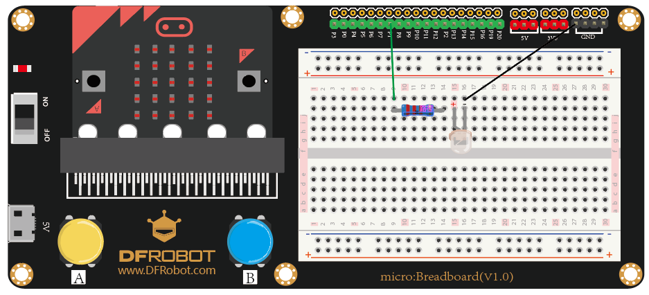
- Learning Target: light up the LED light(the connection is shown below)
- Program Effect: press down button A to turn the LED light on, press button B to turn it off.
- Components: 4 jumper wires, one LED light.
- Pin P0 will be used in the project.

- Screenshot of mind+ graphical codes

- Screenshot of makecode graphical codes

Security Alarm
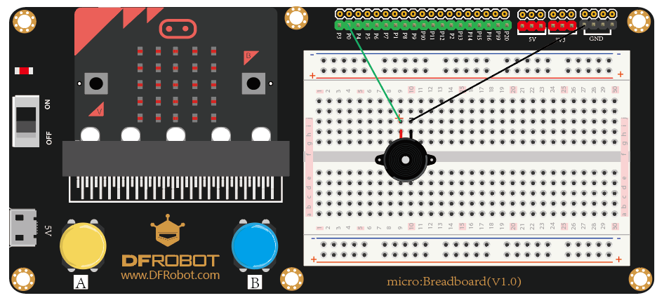
- Learning Target: drive the buzzer
- Porgram Effect: turn on the power, the buzzer starts playing
- Components: two jumper wires, one buzzer
- Pin P0 will be used in this project.

- Screenshot of mind+ graphical codes

- Screenshot of makecode graphical codes

Lighting Console
- Learning Target: adjust the intensity of the light through potentiometer.
- Program Effect: rotate the potentiometer counterclockwise to brighten the LED, clockwise rotation to dim the LED.
- Components: 7 jumper wires. 1 LED light, 1 potentiometer
- Pin: connect the potentiometer to P0, the LED to P1.

- Screenshot of mind+ graphical codes

- Screenshot of makecode graphical codes

Breathing light
- Learning Target: contorl the LED
- Program Effect: the LED light blinks like twinkle stars
- Components: 2 jumper wires, 1 LED light, 1 resistor of 220Ω
- Pin: connect the LED to P1

- Screenshot of mind+ graphical codes

- Screenshot of makecode graphical codes

FAQ
For any questions, advice or cool ideas to share, please visit the DFRobot Forum
