Introduction
This sensor is suitable for detecting soil fertility. It has a 5-30V wide voltage power supply and RS485 output. It can detect nitrogen(N), phosphorus(P), and potassium(K). It has fast response and stable output. It can be used with Arduino UNO R3 and TTL to 485 expansion board to quickly set up tests.
The protection level of the soil sensor is IP68, and it is vacuum filled and sealed with black flame-retardant epoxy resin. The probe material is made of 316 stainless steel, which is rust-proof, waterproof, anti-corrosion, salt-alkali corrosion resistance, and long-term electrolysis resistance. It is more affected by the soil salt content. It is small, can be buried in the soil for a long time, and is suitable for various soil types.
Soil sensors are widely used in agricultural irrigation, greenhouses, flowers and vegetables, grassland and pastures, soil rapid testing, plant cultivation, scientific experiments, grain storage and the measurement of moisture content and temperature of various particulate matter.
Note: Nitrogen, phosphorus and potassium sensor data can only be used as a reference and cannot be as accurate as professional instruments.
Features
- 5-30V wide voltage power supply
- RS485 output, can be used with Arduino
- Fast response and stable output
- Stainless steel probe can be buried in soil or water for a long time
- Resin vacuum filling and sealing, IP68 protection level
Specifications:
- Power supply voltage: DC5-30V
- Power consumption: 0.15W@12V
- Output mode: RS485
- Detection parameters: Nitrogen(N)、Phosphorus(P)、Potassium(K)
- NPK range: 0-2999mg/kg (mg/L)
- Resolution: 1mg/kg (mg/L)
- Accuracy: ≤5% (subject to the actual measuring instrument)
- Protection level: IP68
- Probe material: anti-corrosion special electrode
- Sealing material: black flame retardant epoxy resin
- Working temperature: -40°C~+60°C
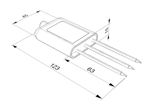
- Size: 123x45x15mm
- Cable length: 2m
Board Overview
| Num | Label | Description |
|---|---|---|
| Brown line | VCC | Power input positive pole, DC5-30V power supply |
| Black line | GND | Power ground wire |
| Yellow line | 485-A | RS485 data line A |
| Blue line | 485-B | RS485 data line B |
Dimensional Drawing

Communication Protocol
1. Basic communication parameters
| Interface | Encoding | Data bits | Parity bits | Stop bits | Error checking | Baud rate |
|---|---|---|---|---|---|---|
| RS485 | 8-bit binary | 8 | None | 1 | CRC | 2400bit/s, 4800bit/s, 9600 bit/s configurable, default 9600bit/s |
2. Data frame format definition
Using ModBus-RTU communication protocol, the format is as follows:
- Time for initial structure ≥4 bytes
- Address code = 1 byte
- Function code = 1 byte
- Data area = N bytes
- Error checking = 16-bit CRC code
- Time to end structure ≥4 bytes
- Address code: It is the address of the sensor, which is unique in the communication network (factory default 0x01).
- Function code: Function indication of the command sent by the host. This sensor reads the register function code 0x03 and writes the register function code 0x06
- Data area: The data area is specific communication data. Note that the high byte of 16bits data is first!
- CRC code: two-byte check code.
Host query frame structure:
| Address code | Function code | Register starting address | Register length | Check code low bit | Check code high bit |
|---|---|---|---|---|---|
| 1byte | 1byte | 2byte | 2byte | 1byte | 1byte |
Slave response frame structure:
| Address code | Function code | Number of valid bytes | Data area 1 | Data area 2 | Nth data area | Check code |
|---|---|---|---|---|---|---|
| 1byte | 1byte | 1byte | 2byte | 2byte | 2byte | 2byte |
3. Communication protocol examples and explanations
3.1. Example: Read the temporary value of nitrogen content at device address 0x01
Inquiry frame (hexadecimal):
| Address code | Function code | Register starting address | Register length | Check code low bit | Check code high bit |
|---|---|---|---|---|---|
| 0x01 | 0x03 | 0x00 0x1E | 0x00 0x01 | 0xE4 | 0x0C |
Response frame (hexadecimal):
| Address code | Function code | Return the number of valid bytes | Nitrogen temporary storage value | Low bit of check code | High bit of check code |
|---|---|---|---|---|---|
| 0x01 | 0x03 | 0x02 | 0x00 0x20 | 0xB9 | 0x9C |
Calculation of temporary nitrogen content value:
- Temporary storage value of nitrogen content: 0020 H (hexadecimal) = 32 => Nitrogen = 32mg/kg
3.2. Example: Read the temporary value of phosphorus content at device address 0x01
Inquiry frame (hexadecimal):
| Address code | Function code | Register starting address | Register length | Check code low bit | Check code high bit |
|---|---|---|---|---|---|
| 0x01 | 0x03 | 0x00 0x1F | 0x00 0x01 | 0xB5 | 0xCC |
Response frame (hexadecimal):
| Address code | Function code | Return the number of valid bytes | Temporary value | Low bit of check code | High bit of check code |
|---|---|---|---|---|---|
| 0x01 | 0x03 | 0x02 | 0x00 0x25 | 0x79 | 0x9F |
Calculation of temporary value of phosphorus content:
- Temporary value of phosphorus content: 0025 H (hexadecimal) = 37 => Phosphorus = 37mg/kg
3.3. Example: Read the temporary value of potassium content at device address 0x01
Inquiry frame (hexadecimal):
| Address code | Function code | Register starting address | Register length | Check code low bit | Check code high bit |
|---|---|---|---|---|---|
| 0x01 | 0x03 | 0x00 0x20 | 0x00 0x01 | 0x85 | 0xC0 |
Response frame (hexadecimal):
| Address code | Function code | Return the number of valid bytes | Temporary storage value | Low bit of check code | High bit of check code |
|---|---|---|---|---|---|
| 0x01 | 0x03 | 0x02 | 0x00 0x30 | 0xB8 | 0x50 |
Calculation of temporary value of potassium content:
- Temporary value of potassium content: 0030 H (hexadecimal) = 48 => Potassium = 48mg/kg
4. Register address
| Register address | PLC or configuration address | Content | Operation | Definition description |
|---|---|---|---|---|
| 001EH | 40031 (decimal) | Temporary nitrogen content value | Read and write | The written nitrogen content value or test value |
| 001FH | 40032 (decimal) | Temporary value of phosphorus content | Read and write | The written phosphorus content value or test value |
| 0020H | 40033 (decimal) | Potassium content temporary value | Read and write | The written potassium content value or test value |
| 03E8H | 41001 (decimal) | Temporary value of nitrogen content High sixteen digits of coefficient | Read and write | Floating point number |
| 03E9H | 41002 (decimal) | The lower sixteen digits of the nitrogen content temporary value coefficient | Read and write | Floating point number |
| 03EAH | 41003 (decimal) | Deviation value of the temporary value of nitrogen content | Read and write | Integer |
| 03F2H | 41011 (decimal) | Temporary storage value of phosphorus content High sixteen digits of coefficient | Read and write | Floating point number |
| 03F3H | 41012 (decimal) | The lower sixteen digits of the coefficient of the temporary storage value of phosphorus content | Read and write | Floating point number |
| 03F4H | 41013 (decimal) | Deviation value of the temporary value of phosphorus content | Read and write | Integer |
| 03FCH | 41021 (decimal) | Potassium content temporary value coefficient high sixteen digits | Read and write | Floating point number |
| 03FDH | 41022 (decimal) | The lower sixteen digits of the potassium content temporary value coefficient | Read and write | Floating point number |
| 03FEH | 41023 (decimal) | Deviation value of the temporary value of potassium content | Read and write | Integer |
| 07D0H | 42001 (decimal) | Device address | Read and write | 1-254 (factory default 1) |
| 07D1H | 42002 (decimal) | Device baud rate | Read and write | 0 represents 2400 1 represents 4800 2 represents 9600 |
Tutorial
Requirements
-
Hardware
- DFRduino UNO R3 (or similar) x 1
- RS485 Shield for Arduino x1
- RS485 Soil Sensor(N&P&K) x1
-
Software
Connection Diagram
Note: Before burning the code, please switch the transceiver mode switch of the expansion board to AUTO, and switch the run/compile switch to OFF. After burning the code, switch the run/compile switch to ON, and select the serial port baud rate to 9600.

Sample Code
uint8_t Com[8] = { 0x01, 0x03, 0x00, 0x1E, 0x00, 0x01, 0xE4, 0x0C };   //N
uint8_t Com1[8] = { 0x01, 0x03, 0x00, 0x1F, 0x00, 0x01, 0xB5, 0xCC };  //P
uint8_t Com2[8] = { 0x01, 0x03, 0x00, 0x20, 0x00, 0x01, 0x85, 0xC0 };  //K
int N, P, K;
void setup() {
  Serial.begin(9600);  /
}
void loop() {
  int N = readN();
  Serial.print("N = ");
  Serial.print(N);
  Serial.print(" mg/kg  ");
  int P = readP();
  Serial.print("P = ");
  Serial.print(P);
  Serial.print(" mg/kg  ");
  int k = readK();
  Serial.print("K = ");
  Serial.print(K);
  Serial.println(" mg/kg  ");
  delay(1000);
}

int readN(void) {
  uint8_t Data[10] = { 0 };
  uint8_t ch = 0;
  bool flag = 1;
  while (flag) {
    delay(100);
    Serial.write(Com, 8);
    delay(10);
    if (readN(&ch, 1) == 1) {
      if (ch == 0x01) {
        Data[0] = ch;
        if (readN(&ch, 1) == 1) {
          if (ch == 0x03) {
            Data[1] = ch;
            if (readN(&ch, 1) == 1) {
              if (ch == 0x02) {
                Data[2] = ch;
                if (readN(&Data[3], 4) == 4) {
                  if (CRC16_2(Data, 5) == (Data[5] * 256 + Data[6])) {
                    N = Data[3] * 256 + Data[4];
                    flag = 0;
                  }
                }
              }
            }
          }
        }
      }
    }
    Serial.flush();
  }
  return N;
}

int readP(void) {
  uint8_t Data1[10] = { 0 };
  uint8_t ch1 = 0;
  bool flag1 = 1;
  while (flag1) {
    delay(100);
    Serial.write(Com1, 8);
    delay(10);
    if (readN(&ch1, 1) == 1) {
      if (ch1 == 0x01) {
        Data1[0] = ch1;
        if (readN(&ch1, 1) == 1) {
          if (ch1 == 0x03) {
            Data1[1] = ch1;
            if (readN(&ch1, 1) == 1) {
              if (ch1 == 0x02) {
                Data1[2] = ch1;
                if (readN(&Data1[3], 4) == 4) {
                  if (CRC16_2(Data1, 5) == (Data1[5] * 256 + Data1[6])) {
                    P = Data1[3] * 256 + Data1[4];
                    flag1 = 0;
                  }
                }
              }
            }
          }
        }
      }
    }
    Serial.flush();
  }
  return P;
}

int readK(void) {
  uint8_t Data2[10] = { 0 };
  uint8_t ch2 = 0;
  bool flag2 = 1;
  while (flag2) {
    delay(100);
    Serial.write(Com2, 8);
    delay(10);
    if (readN(&ch2, 1) == 1) {
      if (ch2 == 0x01) {
        Data2[0] = ch2;
        if (readN(&ch2, 1) == 1) {
          if (ch2 == 0x03) {
            Data2[1] = ch2;
            if (readN(&ch2, 1) == 1) {
              if (ch2 == 0x02) {
                Data2[2] = ch2;
                if (readN(&Data2[3], 4) == 4) {
                  if (CRC16_2(Data2, 5) == (Data2[5] * 256 + Data2[6])) {
                    K = Data2[3] * 256 + Data2[4];
                    flag2 = 0;
                  }
                }
              }
            }
          }
        }
      }
    }
    Serial.flush();
  }
  return K;
}


uint8_t readN(uint8_t *buf, size_t len) {
  size_t offset = 0, left = len;
  int16_t Tineout = 500;
  uint8_t *buffer = buf;
  long curr = millis();
  while (left) {
    if (Serial.available()) {
      buffer[offset] = Serial.read();
      offset++;
      left--;
    }
    if (millis() - curr > Tineout) {
      break;
    }
  }
  return offset;
}

unsigned int CRC16_2(unsigned char *buf, int len) {
  unsigned int crc = 0xFFFF;
  for (int pos = 0; pos < len; pos++) {
    crc ^= (unsigned int)buf[pos];
    for (int i = 8; i != 0; i--) {
      if ((crc & 0x0001) != 0) {
        crc >>= 1;
        crc ^= 0xA001;
      } else {
        crc >>= 1;
      }
    }
  }

  crc = ((crc & 0x00ff) << 8) | ((crc & 0xff00) >> 8);
  return crc;
}
Expected Results
Insert the soil sensor into the soil, and the serial port will print out the nitrogen, phosphorus, and potassium values detected by the sensor.
Note: Nitrogen, phosphorus and potassium sensor data can only be used as a reference and cannot be as accurate as professional instruments.
How to install and use
1、Quick test method
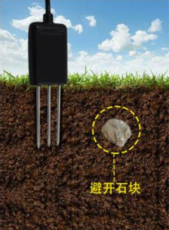
Select a suitable measurement location, avoid stones, and ensure that the steel needle does not touch hard objects. Throw away the topsoil according to the required measurement depth and maintain the original tightness of the soil below. Hold the sensor tightly and insert it vertically into the soil. Do not move left and right when measuring. It is recommended to measure multiple times within a small range of a measuring point and average it.

2、Buried measurement method
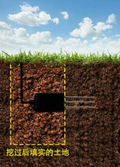
Dig a pit with a diameter >20cm vertically, insert the sensor steel needle horizontally into the pit wall at a predetermined depth, fill the pit tightly, and after a period of stabilization, measurements and recordings can be made for days, months or even longer.

3、Things to note
- The steel needle must be fully inserted into the soil during measurement.
- Avoid strong sunlight directly shining on the sensor, which may cause the temperature to be too high. When using in the field, be careful to prevent lightning strikes.
- Do not violently bend the steel needle, do not pull the sensor lead wire forcefully, and do not drop or violently impact the sensor.
- The sensor protection level is IP68, and the entire sensor can be immersed in water.
- Due to the presence of radio frequency electromagnetic radiation in the air, it is not advisable to leave it powered on for a long time in the air.
FAQ
Possible reasons for no output or output errors:
- The computer has a COM port, but the selected port is incorrect.
- TTL to 485 module operation/programming toggle switch selection is incorrect.
- Wrong baud rate.
- The 485 bus is disconnected, or the A and B lines are connected reversely.
- If there are too many devices or the wiring is too long, power supply should be provided nearby.
- Equipment damage.
For any questions, advice or cool ideas to share, please visit the DFRobot Forum.
