Introduction
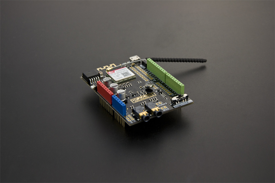
This is a GPRS/GSM Arduino expansion board developed by DFRobot. The capabilities of GPRS, DTMF, TTS speech all in one shield, operating frequency is EGSM 900MHz/DCS 1800MHz and GSM850 MHz/PCS 1900MHz.
It also supports UCS2 encoding data and text data format directly which makes your robot could do TTS voice broadcast at any time. It supports DTMF, once the DTMF feature was enabled, press the keys during a call can be converted into character, and can be used for remote control.
It is controlled by AT commands, you can launch its functions directly through computer serial port or Arduino board. The module was embedded with SIMCom's SIM800H chip with good stability.
More updated feature could be refered to the description of the SIM800H chip. Meanwhile we also show some application of the SIM800H library, it can help you to get familiar with this shield in a easier way.
Specifications
- Working voltage: 6 - 12V
- Low power consumption mode: the current is 0.7mA ( sleep mode )
- Normal consumption mode:(100mA@7V - GSM mode)
- Quad-band 850/900/1800/1900MHz
- GPRS multi-slot class 1~12
- GPRS mobile station class B
- Standard GSM phase 2/2+
- Class 4 (2 W @ 850/900 MHz)
- Class 1 (1 W @ 1800/1900MHz)
- Control method: AT command control
- USB/Arduino switch
- Serial baud rate Adaptive
- Support real time clock (RTC)
- Support TTS and broadcast
- Support DTMF
- LED indicator shows power supply status, network status and operating mode
- Size: 81*53mm
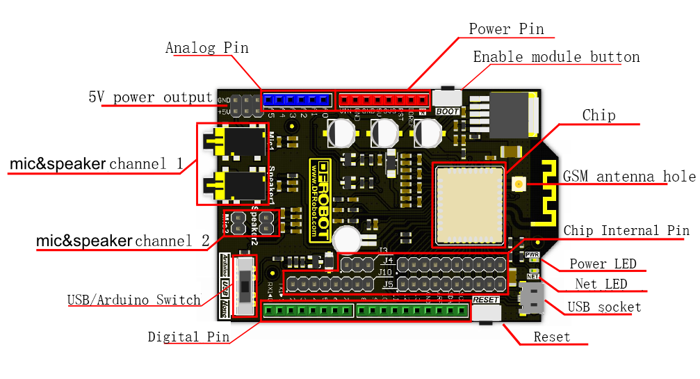
Pin out

Specification:
1 Compatibility
This shield is compatible with Arduino board like Arduino UNO, Arduino Mega1280 and Arduino Mega2560 (5V standard operating voltage).
2 Status light
PWR: Power indicator;
NET: Net connect indicator:
- Off - module are not working;
- 64ms On/800ms Off - module are looking for net;
- 64ms On/3000ms Off - module are connected with net;
3 Enable module button
Press the button for 2 seconds to boot/shut down module.
Note: This button is connected to digital Pin 12, so you can also boot/shut down module by setting the Pin12 value.
4 USB/Arduino Switch
- None: Push to this side when uploading sketch to Arduino board like Uno, Mega except the leonardo.
- Arduino: communicate with Arduino through the sketch.
- USB: communication with PC through the serial(USB cable).
5 mic&speaker channel
These socket and pin are used to play TTS and dialing.
Note: You could change the TTS output channel with AT command. Default channel is channel 1.
Tutorials AT Mode
| NOTE: Note: It needs external power supply (6-12V) for the higher power consumption as the GSM mode. |
How to enter into AT mode ?
1 Preparation
- Insert SIM800H module onto Arduino UNO or any other Arduino card;
- Connect UNO with computer through USB cable
- Connect UNO power jack with an external power supply, 6-12V @ >500mA.
- Set the swith to USB.
2 Boot SIM800H in two ways, anyone of them will work.
- Press the button boot for 2 seconds
- Upload the sketch below.
void setup() {
  //Set pin 12 as output
  pinMode(12, OUTPUT);
  //GSM power on sequence
  digitalWrite(12, HIGH);
  delay(2000);
  digitalWrite(12, LOW);
}

void loop() {
}
- Ready to go
- Choosing the right board and Serial port at Arduino IDE menu bar.
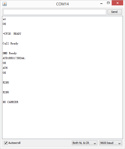
- Open the serial monitor or other Serial Assistant software.
- Choose "Both NL & CR".
- Wait for the NET led to blink as finding net, then you could send some AT commands.
- Otherwise please check the external power supply/ SIM card/ switch position, and then RESET the module.

Typical AT Command list
- AT\r\n
- Return: OK
Description:AT test command, to check if you could enter AT mode.
- ATA\r\n
- Return: OK
Description: answer the phone
- ATH\r\n
- Return: OK
Description: Hang Up
- ATD15982373181;\r\n
- Return: OK
Description: Make a call
- AT+CMGF=1\r\n
- Return: OK
Description: Set SMS form as text mode, when you want to receive SMS via AT commands, you need to send 'AT+CMGF=1' firstly before sending 'AT+CMGR=1'.
- AT+CSCS="UCS2"\r\n
- Return: OK
Description: Set SMS form as UCS2 encoding
- AT+CMGS="00310038003600******0036003500340037"\r\n
- Return: >
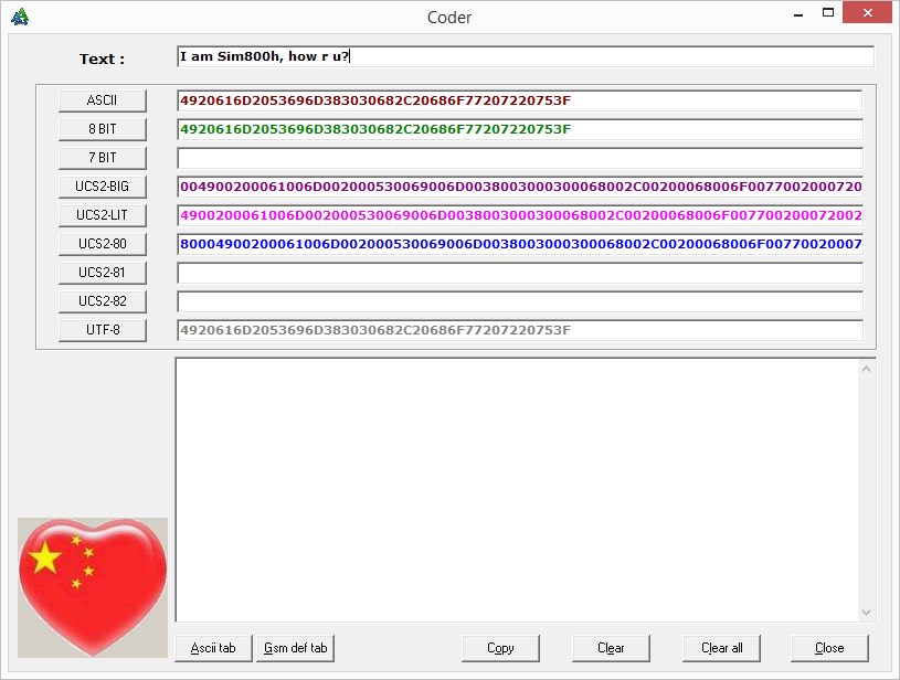
Description:The UCS2-BIG codes inside the quotATion marks is the target phone number to send SMS. when you get ">" characters, enter the message you want to send, content encoding is UCS2 encoding (Set before), then tick the HEX to send, and send "0x1a" expressed as CTRL+Z (0x1A) to send SMS.
- AT+CMGR=1\r\n
- Return: +CMTI:........
Description: Read the message 1, the content "........" :Returned as text messages
- AT+CMGD=1\r\n
- Return: OK
Description: Delete SMS of number 1 in memory.
- AT+CTTS=0\r\n
- Return: OK
Description: Stop the current broadcast
- AT+DDET=1\r\n
- Return: OK
Description: Enable the DTMF function
| NOTE: More AT command could be refered to AT command manual.''' Download AT command manual |
Tutorials about Library Using
Download the library:
| NOTE: SIM800H Hardware Library Due to the incoming serial data is too large, the original Arduino serial cache buffer needs to be changed to be larger, there are two ways:''' |
Extract the hardware.zip
If your Arduino IDE is below 1.5.5 version, cut HardwareSerial.cpp to Arduino\hardware\arduino\cores\arduino and cover the original file.
If it is version 1.5.5 or later, then cut the HardwareSerial.h to Arduino\hardware\arduino\cores\arduino and cover the original file.
Modify the library
If your Arduino IDE is below 1.5.5 version, open the HardwareSerial.cpp file in the Arduino\hardware\arduino\cores\arduino, change # define SERIAL_BUFFER_SIZE 64 to # define SERIAL_BUFFER_SIZE 140;
If the version is 1.5.5 or later, open HardwareSerial.h file and do the same modifications. |
| NOTE: Not compatible with Arduino IDE1.6.*, Recommand Arduino IDE 1.0.6. |
Steps
- Insert the SIM800H GPRS Shield onto UNO board;
- connect UNO to PC with USB cable;
- Use external power supply;
- Turn the switch to the "NONE";
- Open different sketch, select the right board "UNO" and "Srial port", upload sketch to the UNO;
- Don't forget to turn the switch to "Arduino".
- The sketches showing in the chapter are included in the library.
Make a call
Open the sketch "Examples\sim800program\MakeVoiceCall" in Arduino IDE.
/*
Receive Voice Call

This sketch, for the Arduino SIM800H GPRS Shield,enable SIM800H Modular Caller ID, receives voice calls, get the
Answer.

created Dec 2014
by zcl

This example code is in the public domain.
*/

//libraries
#include <sim800cmd.h>

//initialize the library instance
//fundebug is an application callback function,when someon is calling.
Sim800Cmd sim800demo(fundebug);

//the setup routine runs once when you press reset:
void setup(){
    //initialize the digital pin as an output.
    pinMode(13,OUTPUT);
    //initialize SIM800H,return 1 when initialize success.
    while((sim800demo.sim800init()) == 0);
}

void loop(){
 digitalWrite(13,HIGH);//turn the LED on by making the voltage HIGH
 delay(200);
 digitalWrite(13,LOW);//turn the LED off by making the voltage LOW
 delay(200);
}

//application callback function
//Note that not too much to handle tasks in this function
void fundebug(void){
    //answer the call
    sim800demo.answerTelephone();
}
Function description: SIM800H module is initialized, and then dial the number 15982373181.
1. Sim800Cmd sim800demo(fundebug); This function is to recognize incoming call, if there is an incoming call, it will call the fundebug(void) in the end. You could write something to deal with the incoming call: answer or not. But do remember that do not write too much lines in the sub-function.
2. sim800demo.dialTelephoneNumber("15982373181;"); This function is making a dailing. Do not forget the format ";" behind the dail number.
3. sim800demo.sim800init(); This function is to finish the initial module, it's much more easier than the last version product.
AT command:
ATDXXXXXXXXXXX;\r\n
Send SMS
Open the sketch "Examples\sim800program\SendSMS " in Arduino IDE.
/*
TTS Speaker

This sketch, for the Arduino SIM800H GPRS Shield,send a short message to telephone
After initialization success ,enable prompt SMS.

created Dec 2014
by zcl

This example code is in the public domain.
*/

// libraries
#include <sim800cmd.h>

//initialize the library instance
//fundebug is an application callback function,when someon is calling.
Sim800Cmd sim800demo(fundebug);

//the setup routine runs once when you press reset:
void setup()
{
    //initialize SIM800H,return 1 when initialize success.
    while((sim800demo.sim800init()) == 0);
    delay(1000);
    //enable SMS prompt
    sim800demo.setSMSEnablePrompt(OPEN);
}
void loop()
{
    //send message to telephone,use UCS2 code
    sim800demo.sendSMS("00310035003900380032003300370033003100380031","4F60597DFF0C6B228FCE4F7F752800530049004D0038003000300048");
    //while, do not return
    while(1);
}

//application callback function
//Note that not too much to handle tasks in this function
void fundebug(void)
{
}
**Function description:**Enables SMS notification, send a text message.
1. sim800demo.setSMSEnablePrompt(OPEN); This enables SMS notification;
2. sim800demo.sendSMS("00310035003900380032003300370033003100380031","4F60597DFF0C6B228FCE4F7F752800530049004D0038003000300048"); This is to send a text message, the first parameter is a phone number, the second parameter is the content to be sent, both of these parameters is UCS2 encoding.
AT command:
AT+CMGS="00310038003600310036003300360036003500340037"\r\n
Note:
- the text message cannot be longer than 20 characters, or saying 80 UCS2 encoding.
- here need to convert string to UCS2 encoding, you can download the softeware "CharCoder"to transform the string to UCS2 encoding, ps: UCS2-BIG.

Integrated Application
Open the sketch "Examples\sim800program\sim800test " in Arduino IDE.
//libraries
#include <sim800cmd.h>

//initialize the library instance
//fundebug is an application callback function,when someon is calling.
Sim800Cmd sim800demo(fundebug);

//return DTMF value
char rqt = 0;

//the setup routine runs once when you press reset:
void setup()
{
   pinMode(13,OUTPUT);
    //turn the LED off by making the voltage LOW
    digitalWrite(13,LOW);
    while((sim800demo.sim800init()) == 0);
    delay(1000);
    sim800demo.setSMSEnablePrompt(OPEN);
    //enable DTMF
    sim800demo.setDTMFenable(OPEN);
    //registration fundebug2 function
    sim800demo.setDTMFHandlefunction(fundebug2);
}

//the loop routine runs over and over again forever:
void loop()
{
  //calling
  if(rqt == 1)
  {
     rqt = 0;
     sim800demo.sendTTSUCS2Compulsory("003253D1900177ED4FE1FF0C00315F00706FFF0C00305173706F",UCS2);
  }
  else if(rqt == '3')
  {
    rqt = 0;
    sim800demo.sendTTSUCS2Compulsory("6B63572853D1900177ED4FE1",UCS2);
    delay(2000);
    sim800demo.cancelCall();
    delay(2000);
    sim800demo.sendSMS("00310035003900380032003300370033003100380031","4F60597DFF0C6B228FCE4F7F752800530049004D0038003000300048");
  }
  else if(rqt == '1')
  {
    rqt = 0;
    digitalWrite(13,HIGH);//turn the LED off by making the voltage LOW
    sim800demo.sendTTSUCS2Compulsory("706F5DF25F00",UCS2);
  }
  else if(rqt == '0')
  {
    rqt = 0;
    digitalWrite(13,LOW);//turn the LED off by making the voltage LOW
    sim800demo.sendTTSUCS2Compulsory("706F5DF25173",UCS2);
  }
}

//application callback function
void fundebug(void)
{
   rqt = 1;
   sim800demo.answerTelephone();
}

//application callback function
void fundebug2(void)
{
  //get DTMF data
  sim800demo.getDTMFresult(&rqt);
}
Function description:
Initialize the SIM800H module, enable SMS notification, enable DTMF feature. If there is an incoming call, answer it and reset rqt to 1, voice broadcast, if there is any DTMF input, then assign it to rqt and then judge rqt for appropriate action.
AT command:
AT+CMGS="00310038003600310036003300360036003500340037"\r\n'
Library Specification
Initialization part
- Sim800Cmd (): constructor with no arguments, applies only to using the TTS feature, instead of GSM function;
- Sim800Cmd (void (*pRf ()): the constructor with a pointer to function, applies to the TTS feature, and also enable GSM function;
- sim800init (): SIM800H module initialization, complete a series of initial commands;
- sim800open (): turn power on SIM800H;
- sim800close (): power down the SIM800H.
TTS Language part
- setTTSVolume (): set the volume parameter for 0~100;
- setTTSSpeed (): set the broadcast speed rate, the argument is 0~100;
- setTTSVmeSpd (): set the volume and speed simultaneously, the first parameter is volume, the second parameter is speed;
- setTTSParameter (): set the TTS volume, mode, speed, tone, and channel parameters. Please refer to the previous AT instruction;
- sendTTSUCS2Compulsory (char *_s, reModle_t _mdl): compulsory broadcasts, the first parameter is the content to be broadcast, the second is the mode;
- sendTTSUCS2Compulsory (char *_s, reModle_t _mdl, char _chl): compulsory broadcasts, the first parameter is the content to be broadcast, the second is the mode, and the third is a broadcast channel;
- sendTTSUCS2Speak (char *_s, reModle_t _mdl): non-mandatory broadcasts, the first parameter is the content to be broadcast, the second is the mode;
- sendTTSUCS2Speak (char *_s, reModle_t _mdl, char _chl): non-mandatory broadcasts, the first parameter is the content to be broadcast, the second is the mode, and the third is a broadcast channel;
- stopTTSSpeak (): stops the current broadcast;
- getTTSState (): Gets the current broadcast status, if it is broadcasting, then return 1, otherwise return 0.
Dial part
- callReadCSQ (UCHAR *PDA): get the current signal intensity, the *PDA is a buffer of return data, if the acquisition is successful, *PDA will be assigned a value, and the function returns 1, otherwise return 0;
- getCallnumber (char *pnbr): get caller ID, *PDA is a buffer of return data;
- DisplayPhoneNumber (reqmodle_t modle_t): turn on or off the caller ID, the argument is OPEN\CLOSE;
- dialTelephoneNumber (char *_s): call *_s for the number strings, be sure about number followed by ";";
- answerTelephone (void): answer the phone;
- cancelCall (void): hang up the phone;
DTMF part
- setDTMFenable (reqmodle_t modle_t): turn on or turn off the DTMF function, the argument is OPEN\CLOSE;
- setDTMFHandlefunction (void (*pDf ()): registere DTMF callback function, it will callback pDf function when DTMF data is received;
- getDTMFresult (char *PCH): get the DTMF data.
SMS part
- setSMSEnablePrompt (reqmodle_t modle_t): open or close the SMS function, the argument is OPEN\CLOSE;
- setSMSHandlefunction (void (*pDf ()): register message callback function when there are messages coming, callbacks to pDf function;
- getSMSID (char *str): Gets the current message number in the register;
- sendSMS (char *pnber, char *pData): send short messages, the first parameter is the number that is sent to, and the second argument is the data to be sent, remember that both are UCS2 encoding;
- readSMS (char *PADR, char *pData): read short messages, the first parameter is the text number to be read, and the second parameter is the return data buffer;
- deleteSMS (char *PADR): delete SMS, the parameter *PADR is the message number you want to delete.
Download Source
SIM800_Series_AT_Command_Manual_V1.07
FAQ
For any questions, advice or cool ideas to share, please visit the DFRobot Forum.
