Introduction to LoRaWAN
LoRaWAN: An Ultra-Low Power Wireless Communication Technology with a Range of Up to Several Kilometers, Suitable for Long-Term Outdoor Deployment.
If you have a yard, it may contain a variety of flowers and plants, as well as enclosures for animals. The front yard is planted with different types of trees. There could also be a pond where various kinds of fish are raised, and you might even have built a greenhouse for growing flowers and plants.
You have set up a WiFi network composed of multiple routers inside your house to ensure seamless, dead-zone-free WiFi coverage throughout the entire house. Meanwhile, you are fond of smart home and IoT (Internet of Things) devices, such as smart lighting, smart curtains, smart rice cookers, smart air conditioners, smart water heaters, and more. All these smart devices connect to the network via WiFi or Bluetooth.
However, there are also some regrets. This is because you want to use IoT (Internet of Things) devices in your yard as well. For example:
- Install soil sensors on the flowers and plants in the backyard to monitor soil moisture and nutrient levels at any time, and even build an automatic watering system.
- Mount a weather station on the outdoor pavilion for monitoring wind speed, wind direction, outdoor temperature and humidity, illuminance, etc.
- Equip the animal enclosures with air quality sensors to trigger the ventilation system or send notifications for enclosure cleaning.
- Fit the pond with water quality sensors to constantly detect the pH value, ensuring the fish inside live comfortably and prompting timely water changes.
- Install water quality sensors and water level sensors on the water storage tower to monitor water quality safety and achieve the goal of automatic water pumping.
- Set up anti-theft alarm systems in the front yard and backyard to give yourself peace of mind regarding security.
But currently, existing smart home products cannot meet these needs!
- If using WiFi, it consumes too much power to support long-term operation;
- If using Bluetooth, its signal range is only about 10 meters, which is completely unsuitable;
- If using NBIoT, each sensor requires an additional data fee paid to the telecom operator;
- If using wired industrial RS485 products, the wiring installation is complicated and extensive.
Is there a wireless network that requires no wiring, can cover the entire house, and at the same time is standardized, private, and free like WiFi?
LoRaWAN is just such a wireless network: standardized, low-power, with long-range signal coverage, and completely free of charge.
In open areas, LoRaWAN signals can effectively cover a distance of over 4 km! This means LoRaWAN can be used not only in homes but also widely in agricultural, industrial, and urban IoT (Internet of Things) systems!
To meet the wireless communication requirements and regulations in different regions around the world, avoid spectrum interference, and ensure the interoperability and spectrum efficiency of LoRaWAN devices across various regions, LoRaWAN adopts different frequency bands in different areas:
- European Frequency Band: 863-870 MHz band (commonly referred to as the 868 MHz band): This band is widely used in Europe and managed by the European Telecommunications Standards Institute (ETSI).
- American Frequency Band: 902-928 MHz band (commonly referred to as the 915 MHz band): This band is used in the Americas and regulated for use by the Federal Communications Commission (FCC) of the United States.
- Asian Frequency Band: 923-925 MHz band: This band is widely adopted in Asia to comply with the spectrum regulations of different countries in the region.
- Chinese Frequency Band: 470-510 MHz band (commonly referred to as the 470 MHz band): Managed by the Ministry of Industry and Information Technology (MIIT) of China. This band is widely used for low-power wide-area network (LPWAN) communications in China and conforms to China's domestic spectrum regulations.
Product Introduction
This is a LoRaWAN gateway featuring rich functions, stable signal, long communication range and easy operation. It is highly suitable for IoT enthusiasts to use in outdoor IoT development and deployment.
The quality of a gateway depends on its communication range and stability. The DF-LoRaWAN Gateway adopts the 8-channel LoRa baseband chip SX1302 from Semtech. Meanwhile, it has significantly optimized the design of the antenna matching circuit, ensuring stable and reliable communication. Even when other similar products can no longer access the network or communicate normally, the DF Gateway still maintains stable communication.
Easier to Set Up Than a Router: Effortlessly Complete Network Access
DF's LoRaWAN gateway integrates an all-new scanning network access method, enabling automatic node registration and network access. This innovative network access method significantly lowers the complex entry barrier of LoRaWAN. Even beginners in LoRaWAN can quickly complete node network access. Compared with the cumbersome and complicated entry process of similar products, DF makes network access as simple as WiFi connection. Moreover, we also provide detailed tutorials from entry-level to advanced level for you to learn. The hardware, software and tutorials have fully considered your entry threshold, making learning and project deployment completely stress-free.
Integrated SIoT Local Server: Applications Become Simple and Efficient
Previously, if you wanted to use LoRaWAN, there were two methods available:
- The gateway forwards data to a cloud server;
- Set up a local server by yourself, and the gateway forwards data to this local server.
The DF's LoRaWAN Gateway integrates an SIoT Local Area Network (LAN) server. You can directly access the gateway's built-in server via MQTT to read node data. This means you don’t need to set up a server yourself—it not only saves the high costs associated with servers but also significantly simplifies the complexity of your project. All you need to do is read the data, which is as simple as serial communication.
Built-in Data Parser: What You See Is What You Get (WYSIWYG) for Data—No Need to Deal with Complex Unparsed Data
DF's LoRaWAN Gateway comes with a user-editable script-based data parser. This parser can convert raw data into actual physical quantities, such as 28°C, 50cm, and 70% humidity—rather than a jumble of unparsed, incomprehensible data. You can directly call this parsed data within SIoT, display it on a screen, or use it for conditional triggering.
Multiple Networking Methods: Onboard Ethernet and WiFi to Meet Various Networking Conditions
DF's LoRaWAN Gateway is equipped with onboard Ethernet and WiFi, providing multiple communication methods to meet your networking needs under different conditions.
You can also connect to the gateway's hotspot via a computer or smartphone to configure its parameters. When the gateway is installed in hard-to-reach places such as on a wall, connecting to the hotspot enables extremely convenient gateway configuration operations.
Specifications
Power Supply Specifications
- USB-TYPE-C Port: 5V 2A
- DC2.1 Power Supply Port: 7-12V 2A
LoRaWAN Parameters
- Channels: ×8
- Operating Frequency Band: US915 MHz
- Transmission Power: 27dBm MAX
- Protocol: Class A/Class C
- Sensitivity: -140dBm@292bps
- Antenna Connector: SMA
- Antenna: 5dB Gain
Network Parameters
- WiFi: IEEE 802.11 b/g/n (2.4G)
- AP Hotspot: IEEE 802.11 b/g/n (2.4G)
- Ethernet: 1× 100Mbps Ethernet Port
System Parameters
- CPU: Quad-core Cortex-A35, maximum frequency 1.3GHz
- Memory: 512 MB DDR4 RAM
- Flash Memory: 16GB eMMC
- RTC: Built-in
- RST Button: ×1
- BOOT Button: ×1
- Firmware Update: USB-TypeC
Physical Parameters
- Product Dimensions: 142mm (L) × 102mm (W) × 30mm (H) (Antenna Excluded)
- Product Weight: 445g (Including Packaging & Power Supply) / 188g (Gateway Host + Antenna)
- Case Material: Environmentally Friendly ABS
Supported Countries
- United States - USA
- Canada - Canada
- Mexico - Mexico
- Brazil - Brazil
- Argentina - Argentina
- Australia - Australia
Function Description

USB Port:
It supports power supply via the USB interface, with a supply voltage of 5V. Please refer to the function diagram above. You can use various mobile phone chargers or computer USB ports to power the gateway. To ensure the stable operation of the gateway, it is recommended that the power be greater than 10W, corresponding to a current of 2A.
DC2.1 Port:
It supports power supply via the DC2.1 interface, with a supply voltage range of 7V-12V. Please refer to the function diagram above. To ensure the stable operation of the gateway, it is recommended that the power be greater than 20W, corresponding to a current greater than 2A.
First Use
Product Preparation
**Gateway: **
- LoRaWAN Gateway ×1
- LoRaWAN Antenna *1
- TYPE-C Cable *1
Node Device(s):
- LoRaWAN Node Control Terminal *1
- LoRaWAN Node Antenna *1
- TYPE-C Cable *1
Install the gateway antenna and the node antenna
Install the gateway antenna and the node antenna on their respective antenna interfaces as shown in the figure:
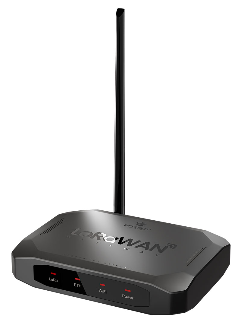
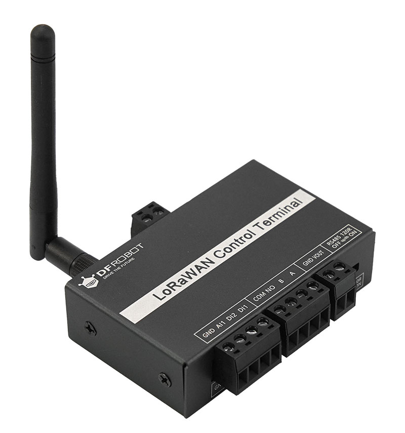
Connect the gateway via the USB port
Use a USB cable to connect the USB port of the gateway to the USB port of a computer. At this point, the gateway will power on and start up. Approximately 1 minute later, the gateway will complete the startup process, and the LoRa indicator light will turn on.
Note: Please use a high-quality USB cable. Poor-quality USB cables may cause insufficient power supply or communication abnormalities, preventing the gateway from working properly.
Install the Driver
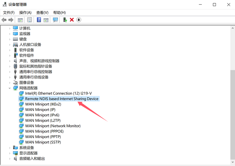
The gateway does not require the installation of external drivers and only needs to use the drivers built into Windows. The usage method is as follows:
Search for and open Device Manager, then right-click on the NDIS device and select Update driver.
Select "Browse my computer for drivers":
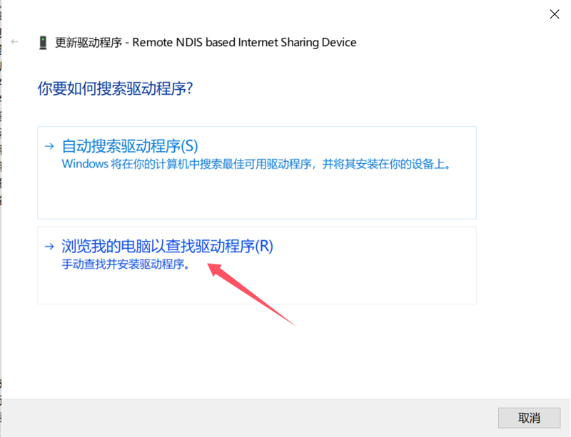
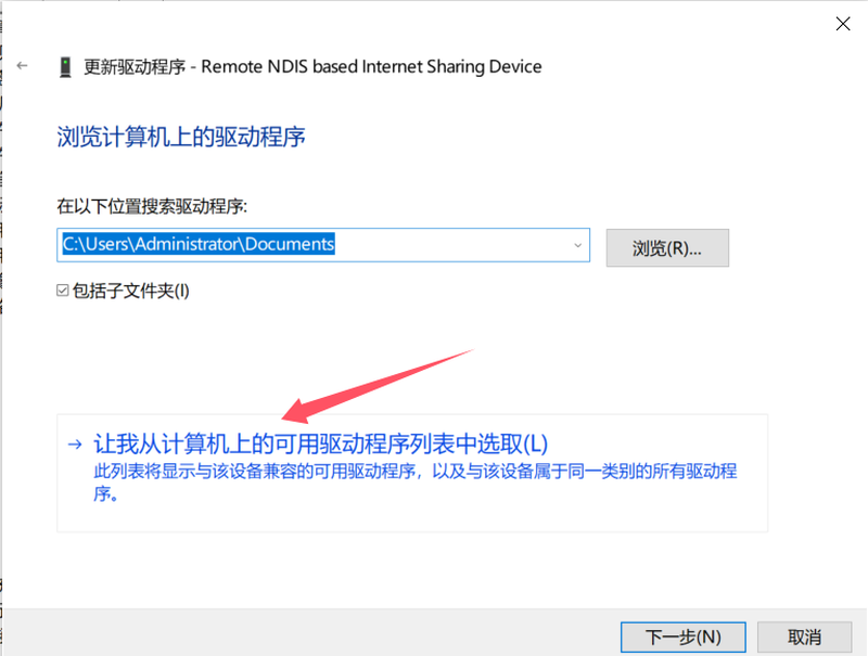
Select "Let me pick from a list of available drivers on my computer":
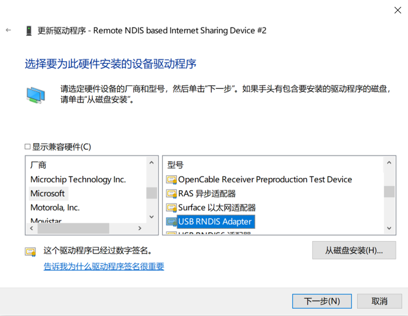
Select "USB RNDIS Adapter" under "Microsoft", then click Next to install.
Log in to the Gateway
Open a browser, enter "10.6.6.6" in the address bar, and press Enter. At this point, a security prompt will pop up on the page, as shown in the figure. Then click the Advanced button to proceed to the next step.
Note: If the LoRa light is not on, it indicates that the gateway has not completed startup. In this case, you cannot log in to the gateway.

After clicking the Advanced button, a security prompt will appear. Then click Proceed to 10.6.6.6 (unsafe) to access the gateway system.
Note: Since the gateway system uses the HTTPS protocol, the browser will pop up a security prompt. Please click with confidence as there is no security risk.

When using the gateway for the first time, a login password interface of the gateway will pop up. Enter the default password "admin" and click "Login" to proceed.
The login password can be changed in the Personal Center.
Register a New Device
If you are using the gateway for the first time, after setting the country and city, you will enter the device registration interface. If you have also purchased a brand-new node device produced by DFRobot, power on the node device at this point, and it will automatically access the network via scanning.
Locate the DVEUI number on the housing of the node device, enter the last three digits, then click Next.
Note:
- New devices added via the scanning method are limited to brand-new DFRobot node devices that have never been connected to a network before.
- If you do not use the automatic new device addition function, please click the "×" in the upper right corner of the pop-up window to close it.
The location of the node device's DEUI number is shown in the figure:

After entering the last three digits of the DEUI, click Next, and the following prompt will pop up. At this point, power on the brand-new node device and click Next.

At this point, the scanning for new devices begins. As shown in the figure below:

The scanning and registration of the device is completed, as shown in the figure:

After clicking the Finish button, the newly added device will now appear in the device list.

View Real-Time Data

Gateway System - Function Description
Overall Overview
The gateway system is divided into a Function Navigation Bar, an Information Bar, a Language & Password Settings Area, and a Function Area.
- Navigation Bar: All main functions of the gateway are accessed through the navigation bar.
- Information Bar: Displays information such as region, network, and time.
- Language & Password Settings Area: Includes functions like Chinese-English language switching, password modification, and region modification.
Function Area: A detailed configuration area and data display area for different functions.

Enter the login password
When you access the gateway system login page, an interface requiring you to enter the login password will appear, as shown in the figure below:
Enter the login password (default password: admin).
Click the "Login" button to access the gateway configuration system.

Change Login Password
You can change your gateway login password at any time in the location shown in the figure below.


Node Device
Function Introduction

Add Node Device
Click the "+" symbol to add a new node device.

A window for selecting node device addition pops up. There are three ways to add a node device:
- Automatic Addition: After entering the last three digits of the node device's EUI number, the system can automatically scan and add the device, enabling quick addition. This method only supports LoRaWAN node devices of the DF brand.
- Manual Addition: Add the device by manually entering node device information such as Device EUI and APPKey. This method supports LoRaWAN node devices of all brands.
- Bulk Addition: Import a CSV file of the node device list to bulk add node devices to the gateway.

Automatic Addition of Node Devices
The automatic node device addition is a simpler and more convenient scan-based device addition method designed for DFRobot's control terminals. You only need to enter the last 3 digits of the DVEUI to add the device.
Click the "+" button to start adding the device.

Select "Automatic Addition" in the pop-up window.

Locate the DEUI device number on the control terminal's housing, then enter its last three digits:

Plug the control terminal into a USB port to power it on, then click "Next":

At this point, the gateway will automatically scan the node control terminal that has just been powered on:

After a few seconds, the node control terminal will be detected and registered successfully:

After clicking the "Complete" button, the newly added device will now appear in the device list.

Manual Addition of Node Devices
Click "Manual Addition" :

After clicking "Manual Addition", the following window will pop up. Fill in the information based on the relevant details of the node device.
The information you enter must be consistent with that of the node device; please refer to the relevant information of the node device for verification.
An example is provided below. After completing the filling, click the "Confirm Addition" button. A prompt indicating "Registration Completed" will then pop up. Click the "Complete" button to finish the registration.

Bulk Addition of Node Devices
When there are a large number of node devices, entering their information one by one is a labor-intensive task and prone to errors. In such cases, you can use the CSV format batch import method to add node devices in bulk. The specific steps are as follows:
Preparing the CSV File:
Enter the node information into a spreadsheet using a spreadsheet application and save it in CSV format. Below is a sample CSV format, which can be imported for testing.

Sample File: Node List.rar
Import Node List:
After clicking the "+", select " Bulk Addition" in the pop-up window:

The bulk addition window pops up:

Click "Upload File" and select the edited CSV file; the system will automatically recognize the device parameters in the CSV file. After confirming there are no errors, click "Confirm Addition"—the node information in the CSV will then be added to the gateway device list.

Added:


Device Settings
Click the gear icon in the device list to access Device Settings.

In the Device Settings function, you can configure settings such as the device's name, type, and whether it is enabled—these are all relatively easy to understand.
Later, we will explain the unique function of data parsing.

Data Parsing (Testing Phase)
The Data Parsing function is a feature that interacts with the SIoT server and is currently in the testing phase.
Developed by DFRobot for the gateway, the Data Parsing function converts raw data into actual values through JS scripts. It allows users to perform formula conversion and parsing on node data by writing JS scripts.
Meanwhile, the parsed data will automatically create a Topic in the gateway's built-in SIoT server, enabling users to obtain this data in real time.
The Data Parsing function includes four built-in features:
- RAW: Outputs raw data; users cannot modify the code here.
- TEXT: Outputs text data; users cannot modify the code here.
- DTU: Parses the raw data related to the control terminal device (SKU: DFR1120) and outputs actual values; users cannot modify the code here.
- Custom: Users can modify the code freely in the custom section, and a new data parsing function will be created after renaming.
Method for custom parsing scripts:
Select the Custom option, then click "Parse/Verify".

A JS script editing window will pop up. Paste the edited script into the code area, name the script in the upper section, and after successful verification, click the Save button to save the script.

JS Script Illustration:
The following code demonstrates converting the obtained hexadecimal data of the node device into text data.
function Decode(hexStr) {
    var hexArray = hexStr.match(/.{1,2}/g).map(function(byte) {
        return parseInt(byte, 16);
    });
    var txt = String.fromCharCode.apply(null, hexArray);
    return { "text": txt };
}
Function Steps:
-
Input Handling: The function receives a hexadecimal string
hexStras input. -
String Splitting: Use the regular expression
/.{1,2}/gto split the string into groups of two characters each. For example, "48656c6c6f" will be split into ["48", "65", "6c", "6c", "6f"]. -
Conversion to Decimal Array: Use
mapandparseInt(byte, 16)to convert each two-character hexadecimal number into a decimal value. For example, "48" → 72, "65" → 101, "6c" → 108, etc. -
Conversion to Text: Use
String.fromCharCode.apply(null, hexArray)to convert the decimal value array into corresponding ASCII characters. For example, [72, 101, 108, 108, 111] → "Hello". -
Return Result: Return an object containing the decoded text:
{"text": txt}.Function Steps:
- Input Handling: The function receives a hexadecimal string
hexStras input. - String Splitting: Use the regular expression
/.{1,2}/gto split the string into groups of two characters each. For example, "48656c6c6f" will be split into ["48", "65", "6c", "6c", "6f"]. - Conversion to Decimal Array: Use
mapandparseInt(byte, 16)to convert each two-character hexadecimal number into a decimal value. For example, "48" → 72, "65" → 101, "6c" → 108, etc. - Conversion to Text: Use
String.fromCharCode.apply(null, hexArray)to convert the decimal value array into corresponding ASCII characters. For example, [72, 101, 108, 108, 111] → "Hello". - Return Result: Return an object containing the decoded text:
{"text": txt}.
- Input Handling: The function receives a hexadecimal string
When a JS script runs correctly and receives valid data, a Topic will be automatically created in the SIoT server.
Project Management
In a LoRaWAN network, you may deploy multiple sets of devices, each corresponding to a different area. As the number of devices increases, it may become inconvenient to manage and monitor them. Therefore, the gateway is equipped with a project management function to facilitate the reasonable classification and management of your devices. As shown in the figure:

Among them, "app-Built-in" is the default project. Click the "Project" icon on the left to enter the Project Settings page, then click the "+" sign in the upper left corner to bring up the New Project page. After entering the project information, you can add a new project.
Note: Only English characters can be used for the project name and description; Chinese characters are not allowed.

Real-time Data
Real-time Data
After a node device is correctly registered on the gateway and powered on, the node will send a network access packet and periodic data packets to the gateway. At this point, incoming data can be viewed on the Data page. The Real-time Data function is mainly used for debugging during device deployment.
The data in Real-time Data is not saved. When you exit the page or re-enter it, the data will be cleared.
At the top of the Real-time Data page, several data filtering tools are provided. You can filter and view data based on conditions such as signal-to-noise ratio (SNR), signal strength, device EUI, and data type. This prevents difficulties in viewing and analyzing data due to excessive data volume.
Additionally, a data export function is available on the right side, allowing you to export the data as a JSON file and save it to your computer.

Data Interpretation:
| 名称 | 解释 |
|---|---|
| Serial Number | The sequence of data reception; click the icon to expand and view detailed data information. |
| Time | The time when data is received is the time set by the gateway. |
| TYPE | Data Type |
| Device Name | The name of the node device, which can be customized by the user. |
| DEUI | The unique EUI number of the device, which is 16 bits in length and usually marked on the device. |
| Device Address | The node device address number automatically assigned by the gateway. |
| Rate | The current communication rate; this value can be modified in the Node APP to adjust the communication rate. |
| SNR | 信噪比,该值越小,信号的信噪比越好 |
| RSSI | 信号强度,该值越小,信号的强度越好 |
| Communication Frequency | Current Communication Frequency |
| Data Parsing | Data received from node devices and parsed by the gateway. |
Send Data
The data sending function is used for device debugging. It allows manual data transmission to node devices, which is applied in debugging and function verification. As shown in the figure below:

Function Explanation:
| Name | Explanation |
|---|---|
| DEUI | The unique EUI number of the device, which is 16 bits in length and usually marked on the device. |
| Data Type | Types of data to send, with two options available: Text: Text format; HEX: Hexadecimal format (must be an even number of digits) |
| Load | The detailed data to be sent |
| Port | 端口号,0-255可选,其中***被内部占用,不可用 |
| Confirmation Packet | Choose whether the node needs to send confirmation data to the gateway after receiving the data. |
| 跳过帧计数器 |
Sending Example:
The following example will demonstrate sending a piece of data to the DTU control terminal to turn on the DTU's relay.
Step 1: Set the rules for the DTU


Step 2: The Gateway Sends Data
Configure the data to be sent as shown in the figure below, then click the "Send Data" button to send the data to the node DTU. Since the device type was set to CLASS-C device just now, you will hear the relay pull-in sound after pressing the "Send Data" button, and after 3 seconds, you will hear the relay release sound.

Gateway Settings
LoRaWAN Settings

Mode Settings
There are three optional modes for LoRaWAN:
- Packet Forwarder (Data Packet Forwarding Mode)
- Basics Station Mode (Class B devices not supported temporarily)
- Built-in Server Mode
Packet Forwarder (Data Packet Forwarder) Mode
Packet Forwarder provides the most basic LoRa data packet forwarding function and does not process content related to the LoRaWAN protocol itself. It only performs data forwarding. For example: After the gateway receives RF (Radio Frequency) data packets (uplink data) sent by end devices, the Packet Forwarder will forward these data packets, along with metadata added by the gateway (such as gateway ID, signal strength, etc.), to the LoRaWAN Network Server (LNS) through a secure IP link. Conversely, when the network server has data to be sent to end devices (downlink data), the Packet Forwarder will also receive these data packets through the same IP link, convert them into radio frequency signals, and send them to the corresponding end devices.
Basics Station Mode
In addition to basic data forwarding functionality, LoRa Basics Station offers several additional features:
- Comprehensive support for communication modes: It supports two communication modes in LoRaWAN, namely Class A and Class C. Class A enables end devices to perform bidirectional communication with the server on demand; Class C keeps end devices' receive windows open for as long as possible, making it suitable for scenarios requiring timely responses to downlink data.
- Centralized management: It features centralized update and configuration management capabilities. Basics Station regularly contacts a separate Configuration and Update Server (CUPS) to check for configuration or software updates, which can even include updates to the underlying operating system. Furthermore, it supports centralized channel planning management, where channel plans and other network parameters are centrally managed by the network server, and Basics Station reads these parameters when establishing a connection.
- Diverse authentication methods: The LNS (LoRaWAN Network Server) and CUPS authenticate Basics Station using TLS (Transport Layer Security). Meanwhile, Basics Station can also use token-based authentication schemes. For embedded gateways running on resource-constrained hardware, token-based schemes are more advantageous due to their lower resource requirements.
- No reliance on local time: Basics Station obtains time synchronization from the network server and does not require a local UTC (Coordinated Universal Time) clock. In Class B mode, it only needs to route the Pulse Per Second (PPS) signal to the concentrator. Synchronization between PPS pulses and global GPS time is achieved through negotiation with the network server, eliminating the need for a GPS module's NMEA interface or other types of interfaces (if a GPS module is available, its information can be used to enhance device health status information).
Built-in Server Mode
The LoRaWAN gateway integrates a lightweight network server, which is referred to as the Built-in Server Mode. It has the following characteristics:
- Convenient Deployment: There is no need to build an additional independent network server. After the device is powered on, a small-scale LoRaWAN network can be quickly established. This mode is suitable for beginners or users who are not very familiar with network setup, greatly simplifying the configuration process.
- Local Data Processing: In scenarios where data isolation and security requirements are extremely high, or where data only needs to be stored and used locally (such as single-point deployment scenarios like individual factories or greenhouses), the Built-in Server Mode can directly collect and process data locally. There is no need to transmit data to a public network server, which improves the response speed of data processing and enhances data security to a certain extent.
Frequency Band Settings

In the frequency band settings, the following frequency bands can be selected, which are:
- FSB1, channel 0~7, 64
- FSB2, channel 8~15, 65
- FSB3, channel 16~23, 66
- FSB4, channel 24~31, 67
- FSB5, channel 32~39, 68
- FSB6, channel 40~47, 69
- FSB7, channel 48~55, 70
- FSB8, channel 56~63, 71
Please select a suitable frequency band plan according to local regulations for the region of use.
Data Filter
If you have a large number of node devices connected and need to filter the node data of a specific part, you can enable the whitelist mode and add relevant values to the whitelist. The node data of the added nodes can be received.
The whitelist provides two methods: Join EUI and Network ID.

Multi-Gateway Settings
On the Multi-Gateway Settings page, you are allowed to add multiple gateways. Typically, this function is used when adding blind-filling gateways to address poor signal quality.
Among the configuration items, the Gateway EUI is the most important identity verification number and must not be filled in incorrectly.

Data Statistics
On the Data Statistics page, data is statistically analyzed by application quantity, signal quality, data packets, and other metrics.

System Information
On the System Information page, various internal information of the gateway is provided for viewing. You can also modify the gateway's system time here.
Meanwhile, interfaces for functions such as firmware update are reserved. However, the firmware update function is not available at present, and a dedicated update software must be used to update the firmware.

Network Tools
In the Network Tools, parameter settings for three functions—WIFI, AP Hotspot, and Ethernet—are provided.
- Only one of WIFI or AP Hotspot can be used at a time.
- After connecting to Ethernet and enabling the Ethernet function, the WIFI connection will be disconnected.

After connecting to WIFI, the gateway configuration system can be accessed via the connected IP address within the local area network (LAN). The location for querying the IP address is shown in the figure. To query the WIFI IP address, you can connect a USB cable to a PC, then enter 10.6.6.6 in the browser to log in to the gateway system.

After the AP mode is enabled, once the computer is connected to the AP, you can enter 10.8.8.8 in the browser to access the configuration system. As shown in the figure:

When the gateway is connected to the Ethernet via the network port, it is inconvenient to check the IP address to log in to the gateway system at this time. In such cases, you can check the IP address of the Ethernet connection by connecting the gateway to a computer via a USB cable or enabling the AP hotspot. After that, you can access the gateway system through the local area network (LAN) IP address.

Application Tools
There are four functional modules in the application tool: Network Tools, LoRa Data Transceiving, VPN, and Node-Red.

Network Tools
In the Network Tools, the Ping tool and the NTP tool are provided.
Ping Tools
-
A network layer connectivity testing tool based on the ICMP protocol, which sends probe packets (Echo Request) to the target IP and monitors response packets (Echo Reply).
Applications in LoRaWAN:
- Verify the gateway's Internet connectivity: Detect whether the gateway can access key network nodes (e.g., network server IP, DNS server, public network address).
- Diagnose backhaul link quality: Measure end-to-end latency (RTT) and packet loss rate to evaluate the stability of backhaul links such as cellular/ Ethernet.
- Fault isolation: If the gateway fails to transmit data, use the Ping test to quickly identify whether the issue is a gateway network fault (e.g., abnormal cellular module, incorrect routing configuration) or a remote service fault.
Network Time Protocol
A UDP-based time synchronization protocol used to calibrate the local system clock to a UTC standard time source (with the error controllable at the millisecond level).
Applications in LoRaWAN:
- Ensure time-sensitive operations:
- Mandatory for Class B mode: Gateways need to broadcast Beacon frames accurately to enable end devices to synchronize reception time slots; time deviation will lead to communication failure.
- Timestamp for uplink data: Mark the reception time of data packets (
rx_time) accurately, which is used by the network server for positioning (TOA/TDOA) calculations.
- Maintain the timing sequence of system logs: Gateway logs and event records rely on a unified time reference, facilitating cross-device fault analysis.
- Dependence for security mechanisms: Some encryption protocols (e.g., session key validity verification) need to rely on time synchronization.

Data Transceiving
The data transceiving function is mainly used as a tool to test whether communication is normal.
LoRa Transmission:

LoRa Reception:

VPN
(typically network servers) over public internet. Their main purpose in the LoRaWAN ecosystem is to address core needs related to security and deployment flexibility.
- PPTP (Point-to-Point Tunneling Protocol): A data link layer tunneling protocol based on PPP encapsulation, used to establish virtual point-to-point connections over IP networks. It was originally designed to provide simple remote access, but as it relies on weak encryption algorithms (such as MPPE combined with MS-CHAPv2) and has known security vulnerabilities, it no longer meets modern network security standards.
- L2TP (Layer 2 Tunneling Protocol): A standardized tunneling protocol (RFC 2661) that transmits PPP frames over network layers such as IP/UDP through encapsulation. Its core value lies in the fact that it must work in conjunction with the IPsec security suite (L2TP/IPsec). IPsec provides strong encryption (e.g., AES), data integrity verification (e.g., HMAC-SHA), and mutual authentication (e.g., pre-shared keys or certificates), thereby building a VPN tunnel that meets industrial-grade security requirements.

Node-RED
Node-RED is a flow-based low-code development tool specifically designed for the Internet of Things (IoT).
By dragging and dropping nodes, you can quickly build data flows and automated tasks.
With Node-RED, you can easily process data from LoRaWAN devices, enabling data parsing, storage, visualization, and automated control.
Click the "Start" button to access Node-RED.
For detailed instructions, please refer to the Node-RED content below.

Restore Factory Settings
Press and hold the RST button on the back of the gateway for 10 seconds without releasing it. After the gateway starts up, the factory settings will be restored. As shown in the figure:

Node-RED Visual Programming
Access Method
- Access the gateway configuration system.
- From the navigation bar, go to Application Tools > Node-Red.

The main interface after accessing Node-Red:
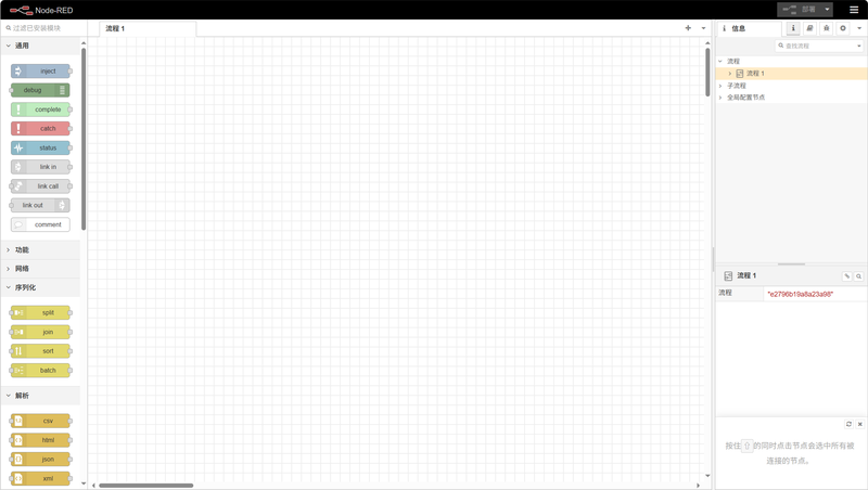
Example: Obtain the Device List
In this example, the built-in demo will be called to obtain the list of devices of nodes in the current gateway. The method is as follows:
Click the menu icon in the upper right corner, and then click "Import" in the drop-down menu:

In the pop-up window, select "Examples". There are 4 built-in demos. Choose the demo named "01-get Node List", and finally click the "Import" button to import the program.
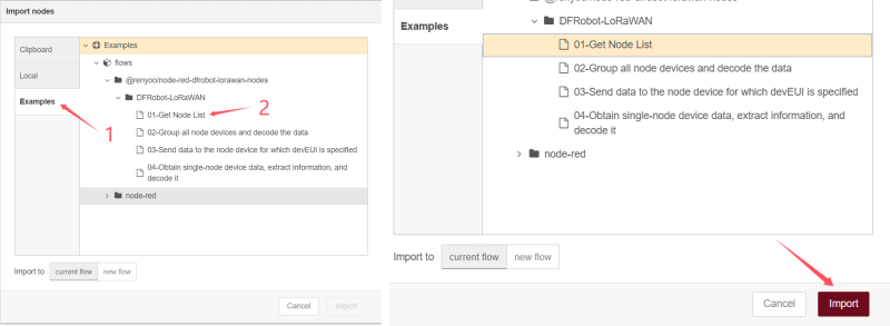
The imported program is as follows:

Click the debug icon in the upper right corner to open the debug window:

Click the red "Deploy" button to deploy the program:

Click the small square on the far left of the timestamp module to inject the timestamp. You can then view the current node device list and device information in the debug window on the right, as shown in the figure:

For more detailed instructions on using Node-RED, please refer to the official Node-RED documentation: https://nodered.org/docs/
SIoT Local Area Network (LAN) Server (Functional Test Version)
What is SIoT?
SIoT is a local area network (LAN) server based on the MQTT protocol launched by DFRobot, which allows the one-click creation of a local IoT (Internet of Things) server. Moreover, it is built into the LoRaWAN gateway in a completely free manner.
The SIoT function is currently in the test version and only supports the Chinese interface. You can use a browser translation plug-in to translate it into English. In the future, an English interface will be added through firmware update.
Access SIoT
First, connect the gateway to the computer.
- If using a USB connection, the address to access SIoT is: 10.6.6.6:8080/
- If using an AP hotspot connection, the address to access SIoT is: 10.8.8.8:8080/
- If using an Ethernet or WIFI connection, the address to access SIoT is the IP address followed by ":8080". For example: 192.168.9.1:8080
SIoT Login Interface:
- Username: siot
- Password: dfrobot

The SIoT Main Interface After Accessing:
The SIoT built into the current gateway only supports the Chinese interface. In the future, an English interface will be added by updating the firmware.

Default Topic
The system automatically creates 4 default topics, which are:
- siot/lora/84BE8B2070C66A7E/rssi: Read RSSI and save it in this topic
- siot/lora/84BE8B2070C66A7E/snr: Read SNR and save it in this topic
- siot/lora/84BE8B2070C66A7E/battery: Read battery level and save it in this topic
- siot/lora/84BE8B2070C66A7E/raw: Read raw value and save it in this topic
Naming rule: siot/lora/Node Device DEUI/Data type to be read.
The topic of SIoT is deeply bound to the data parsing function of LoRaWAN. When new custom parsing code is added to the data parsing function and runs correctly, the system will automatically create a new topic in SIoT.
Create a Topic
Click Create New Topic to create a new Topic:
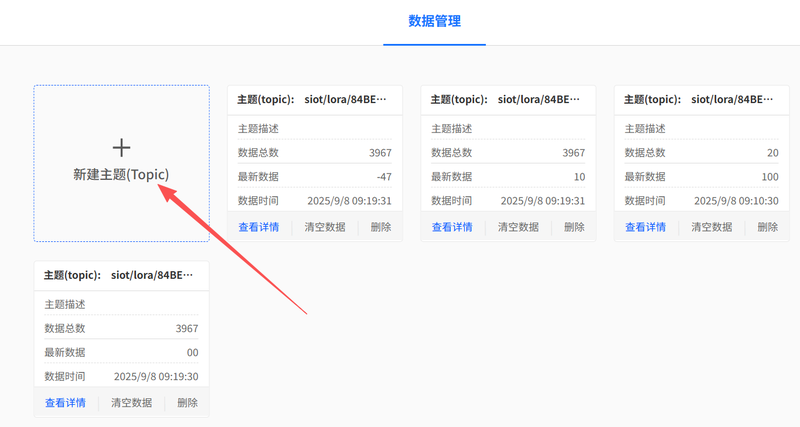
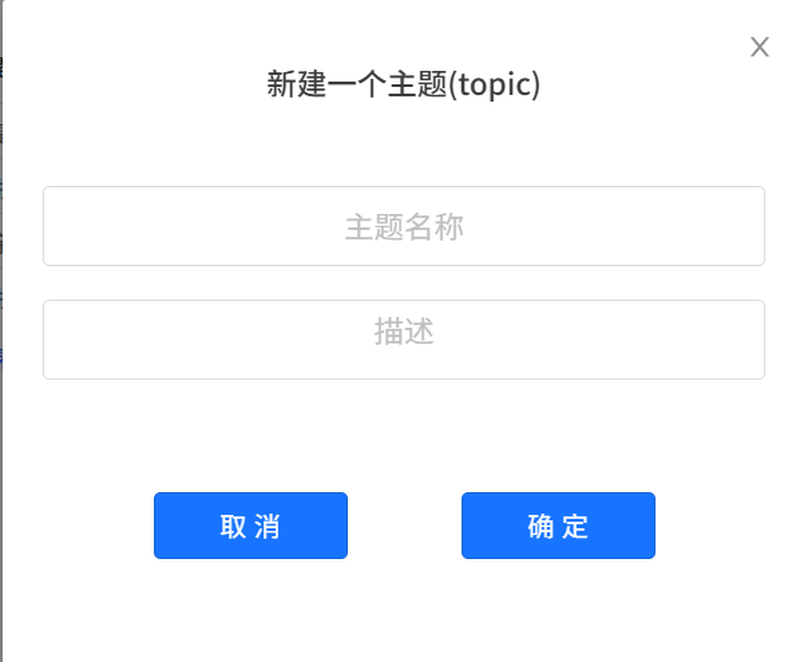
A "Create a New Topic" dialog box will pop up. You need to name the topic and add a descriptive note.
A topic can serve as an independent SIoT topic and be named arbitrarily.
It can also be used to read LoRaWAN-related data. If you intend to read LoRaWAN-related data, you must follow specific naming rules.
SIoT Communication Example
Download the MindPlus software: www.MindPlus.cc
Ensure the computer running MindPlus and the gateway are on the same local area network (LAN).
Open the MindPlus software and click the visualization window:

Click Create New Project to create a blank project:

A dialog box will pop up. Name the project, then click OK.

After clicking OK, the project is added successfully:

Click the Edit button on the project you just created to edit the project parameters:
Server Address: Enter the address of the current gateway connected to the local area network (LAN):
- If using a USB connection, the address is: 10.6.6.6
- If using an AP hotspot connection, the address is: 10.8.8.8
- If using an Ethernet or WIFI connection, the address needs to be checked in the gateway
In the figure, a USB connection is used as an example, and the address is 10.6.6.6. The username and password remain unchanged.
After clicking Finish, the setup of the IoT platform is completed.

Drag in the Single-line Text module, set the topic for the module to display data, and select any one (e.g., raw).

Open SIoT in the gateway, find the topic named "raw", and click "View Details" to enter:

A detailed topic data page will pop up. Enter "hello" in the input box and click Send:

At this point, if you check the data on the visualization panel in MindPlus again, you will see that it has changed—it has received and displayed "hello".

If the node device with this DEUI number continuously reports data, both SIoT and the visualization panel within the local area network (LAN) will continuously receive the data.
Connect to the Cloud
Connect to TTN using Packet Forwarder
Register an account on TTN: https://www.thethingsnetwork.org/
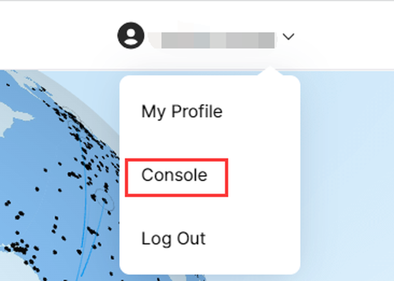
Select "Console" in the top-right corner of the page.
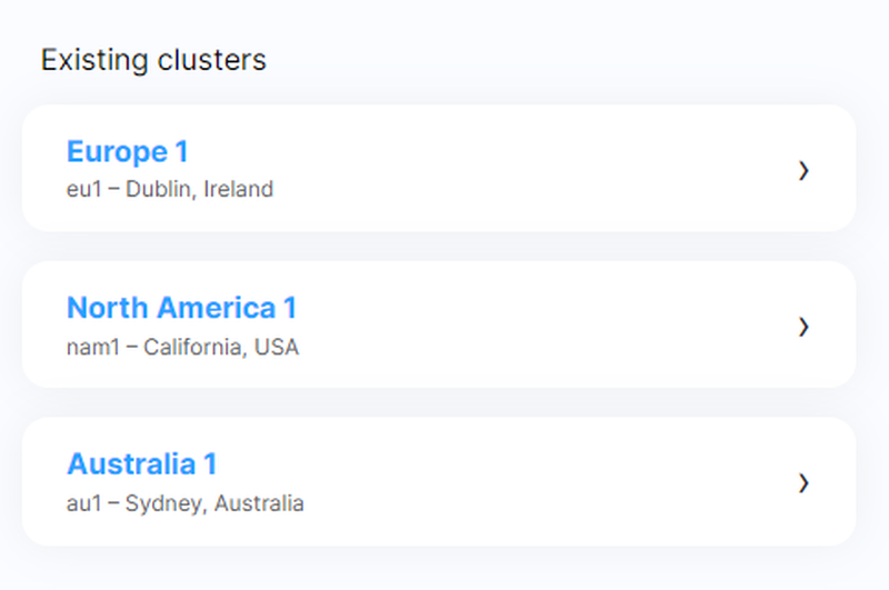
Select the corresponding region
Register a gateway on TTN
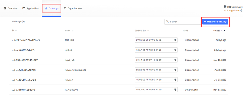
Enter the Gateway EUI; the Gateway EUI can be obtained from the web configuration page.
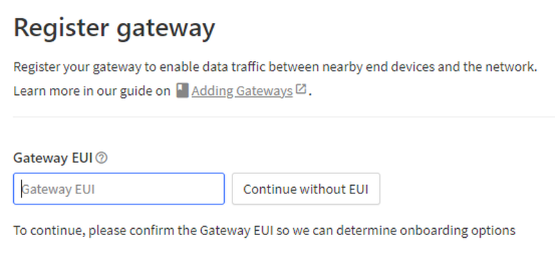

Then select the corresponding frequency to complete the gateway registration.
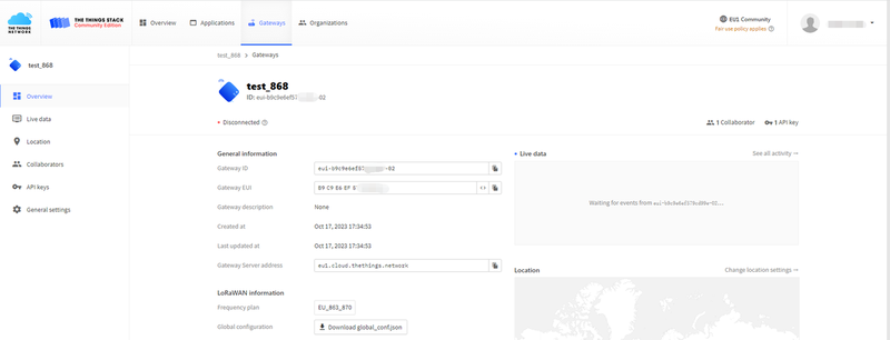
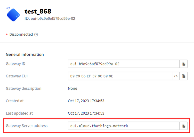
Connect the gateway to a network cable. Now return to the gateway's configuration page, set the mode to "Packet Forwarding Mode", replace the "Server Address" with the "Gateway Server Address" from TTN, then click the Confirm button to save the configuration.

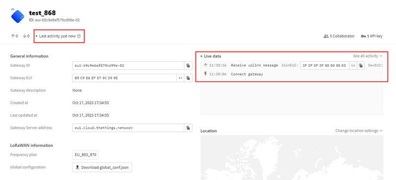
At this point, return to the TTN page, and you will see that the gateway has been connected.
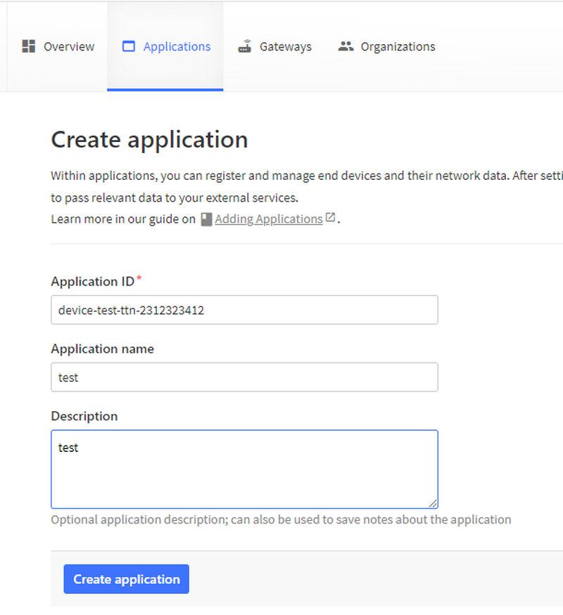
If you want to add a node device, create a new application on the TTN page.

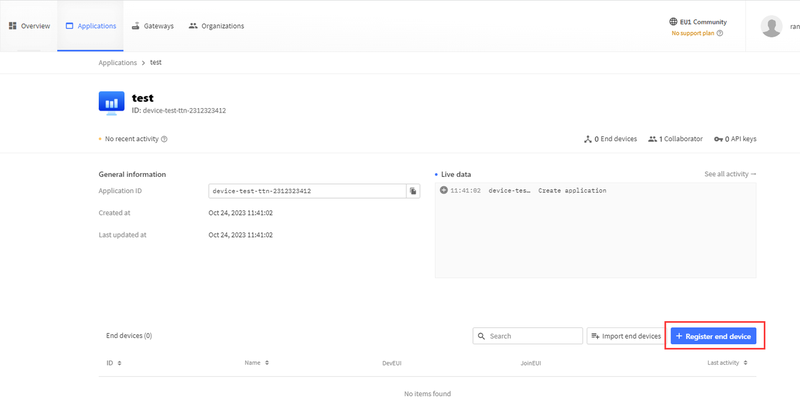
Create a new node device in the current application
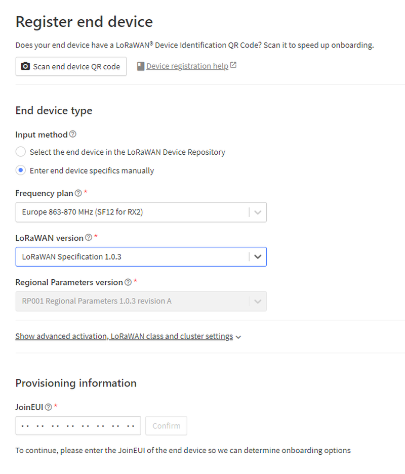
Fill in your node information in sequence to complete the node creation.
After completing the creation, you can observe the node device. The device can successfully access the network through the gateway's Packet Forwarding Mode, and you can also view the data reported by the node.
Connect to LORIOT using Packet Forwarder
Visit loriot.io
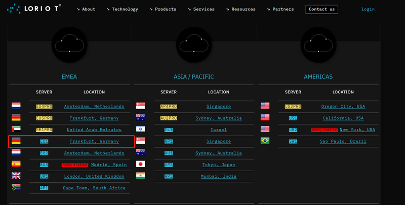
On the login page, select Germany, Frankfurt
Log in.
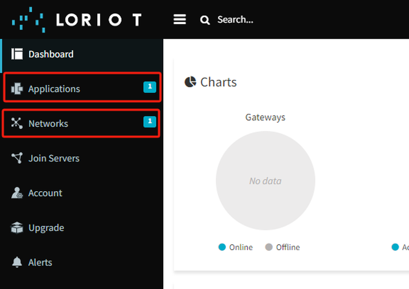
Add a gateway device in "Networks"; add a node device in "Applications".
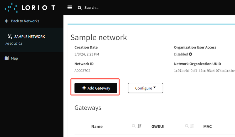
Use its built-in template "Sample Network"
Select "Packet Forwarder Semtech"

Fill in the MAC address and the gateway's EUI as instructed
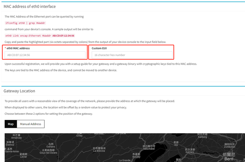
Then click Register Gateway at the bottom of the page.
On the LoRaWAN gateway web interface, switch the mode to Packet Forward and fill in the corresponding information.

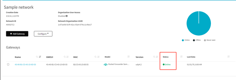
You can already see that the gateway is online on the LORIOT page.
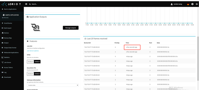
Add a node device in "Applications", and you will be able to see the messages reported by the node.
Connect to TTN using Basic Station
The preparation steps are the same as the Packet Forwarder steps above: register a TTN account, then register the gateway.
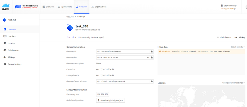
Three key configuration pieces of information are required: 1. "Gateway Server Address", 2. Create an API key and copy it down, 3. Prepare the certificate.
First, create an API key first.

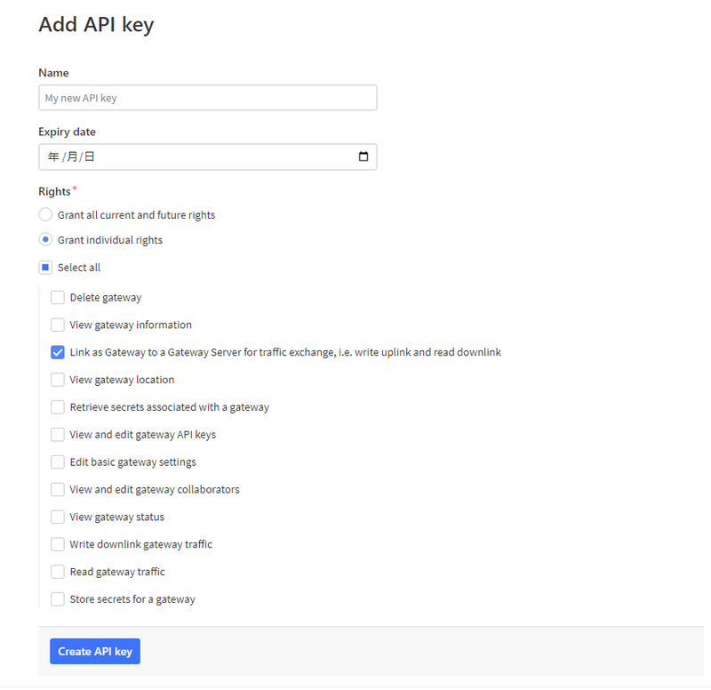
Copy down the API key
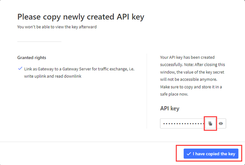
Return to the gateway's web configuration page, set the mode to "Basic Station", and fill in the three pieces of configuration information prepared earlier.

For example:
- Server Address: eu1.cloud.thethings.network
- Client Token: NNSXS.EKPBFIZFL3TUZUWFFHLGL5L6LEY76GRJZ4EC3OA.N5VGFCNIAZN7ISWTNCWNBFDQRPKWFZOPU3OTQ7TMDLPBMF4FTKBA
- CA Certificate: trust.pem
The CA certificate can be obtained via the provided URL.
Connect the gateway to the network using an Ethernet cable.
Then add the node device to the TTN application. After resetting the node, you will be able to see the data reported by the gateway on TTN.
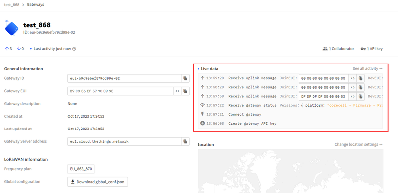
Connect to LORIOT using Basic Station
Refer to the previous steps for connecting to LORIOT using Packet Forwarder.
Here, select "Basics Station Semtech" when choosing the gateway type.
Fill in the MAC address and the gateway's EUI as instructed, navigate to the gateway page, click "Certificate", and generate the "TLS Certificate".
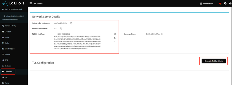
Download the three files below, and map them to "CA Certificate", "Client Certificate", and "Client Key" on the gateway page respectively.
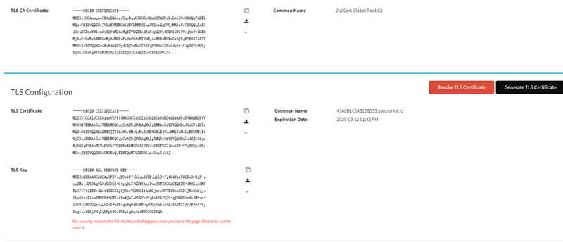
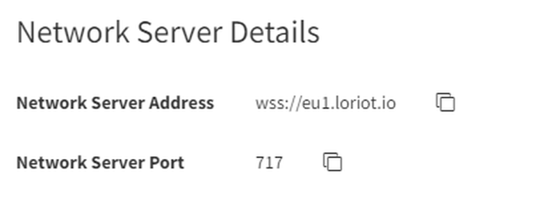
Server and Port Number
Connect to AWS using Basic Station
Using the Basic Station Mode LNS Server
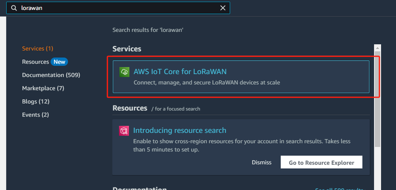
Search for "lorawan" on the homepage

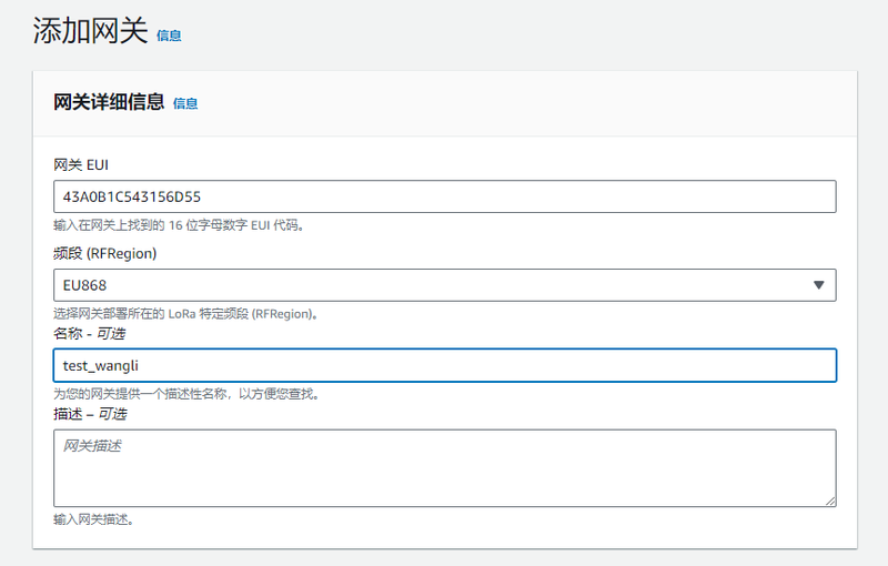
Click "Add Gateway"
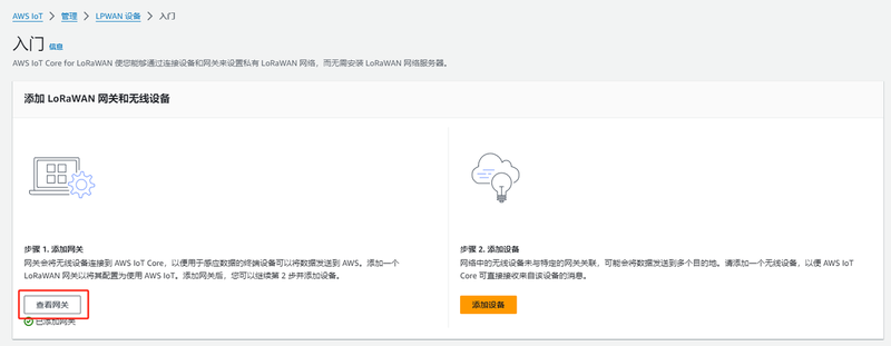
Click "Add Gateway", fill in the relevant information, scroll to the bottom and click "Add Gateway".
Click "Create Certificate"
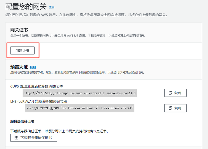
Download the certificates from these two locations; there are a total of four files.

Select the default values and create.

Copy down the server URL, remove the trailing ":443" and the leading "wss://", then enter the resulting content into the LoRaWAN gateway. The server port is 443.

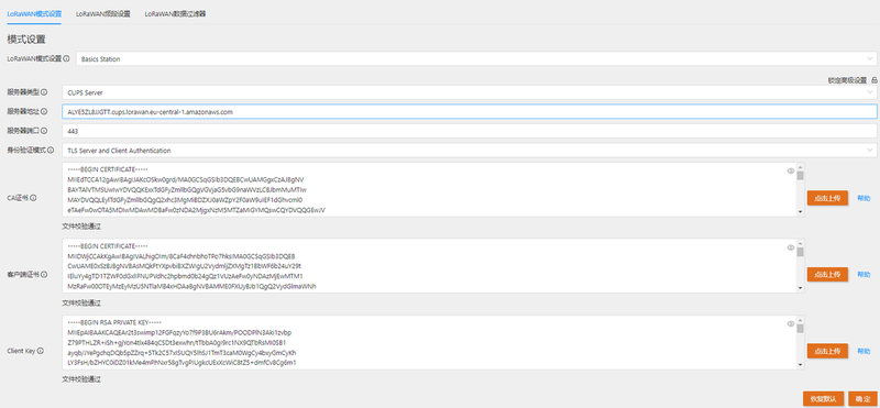
On the LoRaWAN gateway page, enter "lns.trust" for "CA Certificate", the .pem file (content) for "Client Certificate", and the .private.key file (content) for "Client Key".
Using the Basic Station Mode CUPS Server
Refer to the LNS mode mentioned in the previous text.
Among the four downloaded files, one is named "cups.trust". On the LoRaWAN gateway page, enter "cups.trust" for "CA Certificate", the content of the .pem file for "Client Certificate", and the content of the .private.key file for "Client Key".
It can be seen that the connection to AWS has been successfully established.
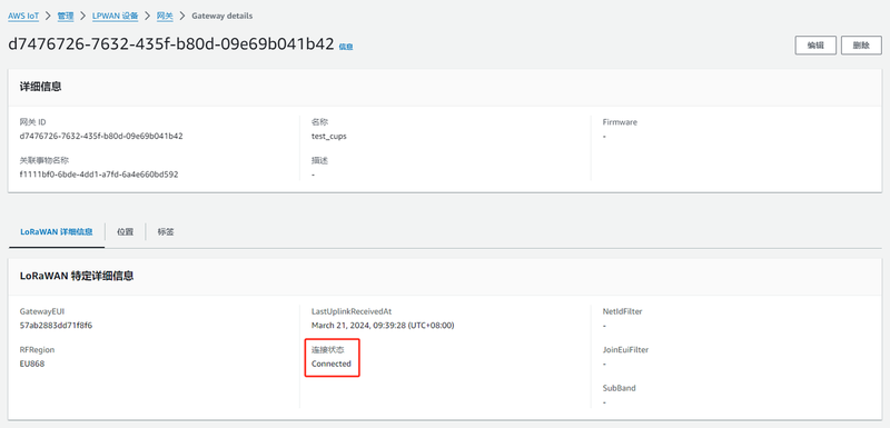
Add Devices and View Device Information

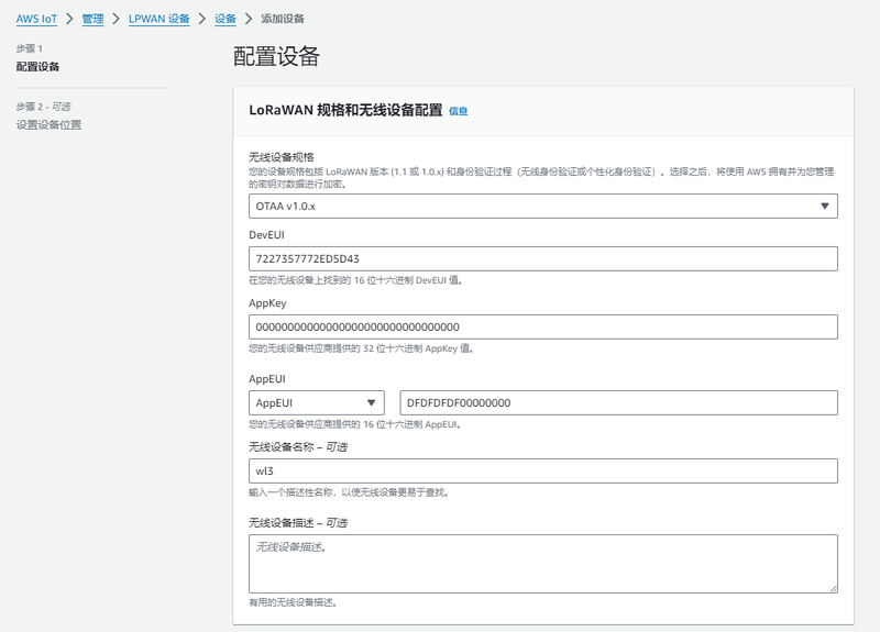
Enter the various types of information about the device
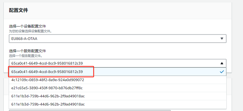
Select the default for the configuration file.
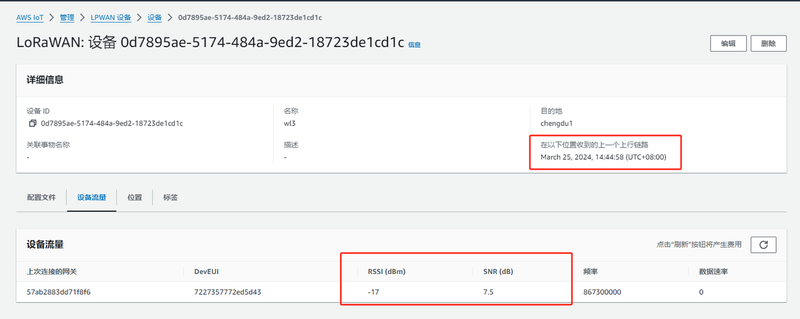
After creating the device, wait for 1 to 2 minutes, and you will be able to see the time of the device's data report and the signal strength.
More Documents
For any questions, advice or cool ideas to share, please visit the DFRobot Forum.
