1. Product Description
1.1 Product Overview
FireBeetle 2 ESP32-C5 is a low-power IoT development board equipped with Espressif's ESP32-C5 module. Targeting smart home and a wide range of IoT scenarios, it integrates high-performance computing, multi-protocol support, and intelligent power management, providing a highly reliable, flexible, and long-lasting solution for various deployment needs.
Support for 2.4 & 5 GHz Dual-Band Wi-Fi 6
ESP32-C5 is Espressif's first chip supporting dual-band Wi-Fi 6 (2.4 G and 5 G). Compared to the 2.4GHz band, 5GHz offers higher transmission rates, lower latency, and less interference, providing a more stable and low-latency wireless connection. Meanwhile, Wi-Fi 6 technology significantly increases network capacity and reduces device power consumption through OFDMA (Orthogonal Frequency Division Multiple Access) and TWT (Target Wake Time) mechanisms, extending battery life and enabling long-term device operation.
With dual-band Wi-Fi 6 support, FireBeetle 2 ESP32-C5 can meet the dual demands of high throughput and low power consumption in scenarios such as smart homes and IoT.
Multi-Protocol Integration, Expanding Wireless Connectivity
The development board supports Wi-Fi, Thread, BLE, and Zigbee protocols, enabling the construction of Matter Wi-Fi/Thread end devices to achieve cross-platform interconnection of smart home devices. Combined with an external MCU, it can also serve as a Thread border router, Matter gateway, or Zigbee bridge to cover complex scenario requirements.
Efficient Power Management, More Flexible Deployment
FireBeetle 2 ESP32-C5 provides efficient and easy-to-use power management, offering reliable and flexible power supply solutions for various deployment needs.
- Diverse power supply methods: Supports Type-C, 5V DC, and solar input for lithium battery charging, solving deployment difficulties in scenarios without power sources (such as rooftops, balconies).
- Solar-optimized PMIC (Power Management Integrated Circuit): Adopts the same solar power management chip as the Solar Power Management Module 5V@1A, maximizing the current output capability of the input power source and the power generation efficiency under different lighting conditions.
- Intelligent monitoring and energy saving: Integrates battery level monitoring function with low-battery warning support; provides a set of controllable 3.3V power output, which can cut off the power supply of external sensors to further reduce power consumption.
1.2 Product Features
- Equipped with ESP32-C5-WROOM-1-N4 module
- Main frequency up to 240 MHz, built-in 384 KB SRAM, 320 KB ROM, 4 MB FLASH
- Supports 2.4 G and 5 G dual-band Wi-Fi 6, lower latency, lower power consumption
- Supports other communication protocols such as BLE, Zigbee, Thread
- Supports flexible and efficient power management
- Supports solar charging, deployment without power cords
- Battery level detection to know device power information
- Supports 3.3V controllable power output, supplying power on demand
- Ultra-low power consumption, deep-sleep current in 21μA
- On-board GDI interface for easy connection to screens
- PH2.0 battery interface for convenient battery connection
- Supports C/C++ and MicroPython programming
2. Technical Specifications
2.1 Product Parameters
- Basic Parameters
- Operating voltage: 3.3V
- Type-C input voltage: 5V DC
- VIN input voltage: 5V DC or 4.5-6V solar panel
- Maximum charging current: 0.5A
- Sleep current: 21μA (deep sleep mode, battery-powered)
- Module size: 25.4x60mm
- Hardware Information
- Processor: RISC-V single-core processor
- Main frequency: 240 MHz
- SRAM: 384KB
- ROM: 320KB
- Flash: 4MB
- LP SRAM: 16KB
- WIFI
- WIFI frequency bands: 2.4 GHz and 5 GHz, 1T1R
- WIFI protocols: IEEE 802.11a/b/g/n/ac/ax
- IEEE 802.11a/b/g/n (data rate up to 150Mbps)
- IEEE 802.11ax (20 MHz-only non-AP mode)
- WIFI modes: Station mode, SoftAP mode, SoftAP+Station mode, and promiscuous mode
- Bluetooth
- Bluetooth protocols: Bluetooth 5, Bluetooth mesh
- Bluetooth frequencies: 125 Kbps, 500 Kbps, 1 Mbps, 2 Mbps
- IEEE 802.15.4
- Compatible with IEEE 802.15.4-2015 protocol
- Frequency band: 2.4GHz
- Data rate: 250Kbps
- Supports Thread 1.3, Zigbee 3.0
- Interface Pins
- Digital I/O x18
- LED PWM controller with 6 channels
- SPI x1
- UART x3 (LP UART x1)
- I2C x2 (LP I2C x1)
- I2S x1
- Infrared transceiver: 5 transmit channels, 5 receive channels
- 1x 12-bit SAR ADC with 7 channels
- DMA controller with 3 receive channels and 3 transmit channels
2.2 On-board Function Diagram
- Type-C: USB interface
- Charge: Charging indicator light
- Off: No power connected or fully charged
- Steady on: Charging in progress
- 15/D13: On-board LED pin
- RST: Reset button
- 28/BOOT: IO28 pin/BOOT button
- BAT: Lithium battery interface, supporting 3.7~4.2V
- IO1: Battery voltage detection pin
- 3V3_C: IO0 controls 3.3V power output, default off, can be turned on with high level.
- GDI: GDI display interface
- ESP32-C5: Module model is ESP32-WROOM-1-N4

IO expansion board

2.3 On-board Function Pin Definition
GDI Display Interface
This interface is a DFRobot-specific GDI display interface, which uses an 18pin-FPC cable to connect to the screen, making screen connection more convenient.
The pin mapping is as follows:
| FPC PINS | Firebeetle 2 ESP32-C5 PINS | Description |
|---|---|---|
| VCC | 3V3 | 3V3 |
| LCD_BL | 15/D13 | Backlight |
| GND | GND | GND |
| SCLK | 23/SCLK | SPI clock |
| MOSI | 24/MOSI | Master output, slave input |
| MISO | 25/MISO | Master input, slave output |
| LCD_DC | 8/D2 | Data/Command |
| LCD_RST | 26/D3 | Reset |
| LCD_CS | 27/D6 | TDT chip select |
| SD_CS | 3/A2 | SD card chip select |
| FCS | NC | Font library chip select |
| TCS | 6/D12 | Touch chip select |
| SCL | 10/SCL | I2C clock |
| SDA | 9/SDA | I2C data |
| INT | 7/D11 | INT |
| BUSY | NC | Tear-proof pin |
| X1 | NC | Custom pin 1 |
| X2 | NC | Custom pin 2 |
When connecting the screen with an FPC cable, you only need to configure the corresponding pin numbers according to the GDL demo, usually only three pins need to be configured according to different main controllers.
Displays supporting GDI:
- 1.54" 240x240 IPS Wide-Angle TFT Display
- 1.8" 128x160 IPS TFT LCD Display
- 2.0" 320x240 IPS Wide-Angle TFT Display
- 2.8" 320x240 IPS TFT Resistive Touch Display
- 3.5" 480x320 IPS TFT Capacitive Touch Display
- 1.51" OLED Transparent Screen
IO Functions

Pin overview is as follows:
- Power: Power pins
- VIN: 5V DC input or 5V solar panel
- 3.3V: 3.3V regulated power output
- 3V3_C: IO0 programmably controls 3.3V power output, default off, turns on with high level
- GND: Common ground pin
- GPIO: ESP32 default GPIO number
- Arduino: GPIO mapping of FireBeetle 2 ESP32-C6 in Arduino
- ADC: ESP32 default analog-to-digital conversion pin
- I2C: I2C interface
- SDA/SCL: I2C mapping of FireBeetle 2 ESP32-C5 in Arduino
- LP_SDA/SCL: Low-power I2C pins
- UART: UART interface
- LP_TX/RX: Low-power UART pins
- SPI: SPI mapping of FireBeetle 2 ESP32-C5 in Arduino
- SDIO: ESP32 default SDIO pins
- JTAG: Debug interface
3. First Use
3.1 Adding the Board
Please click the link below to view the detailed steps for adding the board:
https://wiki.dfrobot.com.cn/Add_ESP32_board_to_Arduino_IDE
3.2 Selecting the Development Board and Serial Port
After the ESP32 board is installed, the next step is to select the SDK corresponding to Firebeetle 2 ESP32-C5.
-
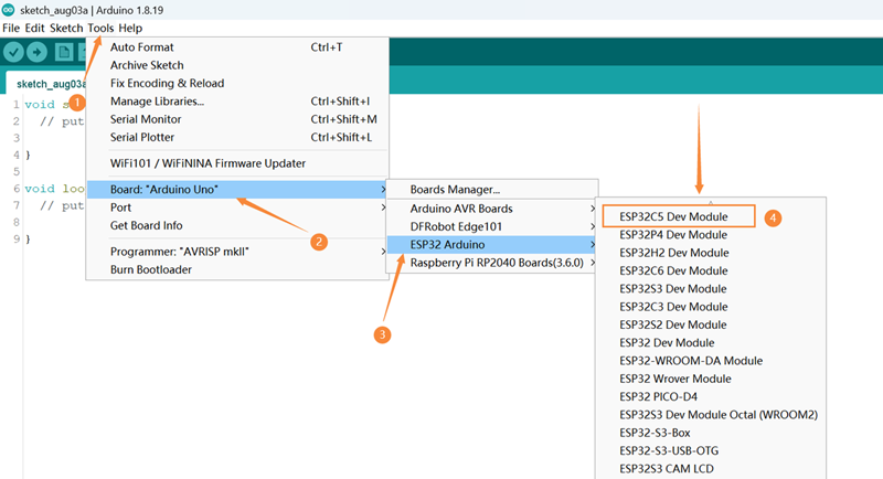
Open Tools -> Board: -> ESP32 Arduino to see the list of development boards, as shown in the figure below, select ESP32C5 Dev Module.

-
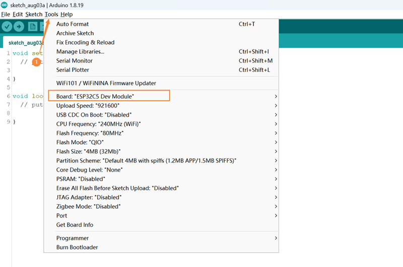
Open Tools again, and you can see Board: "ESP32C5 Dev Module".

-
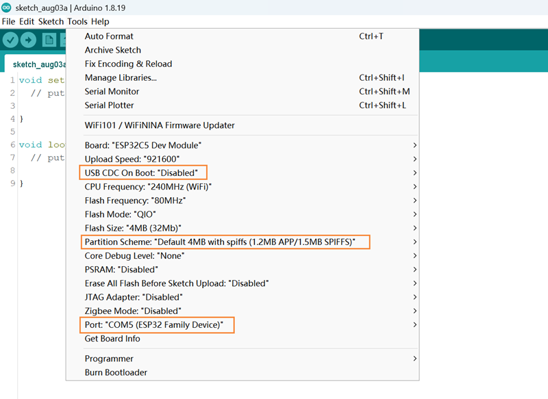
Connect the Firebeetle 2 ESP32-C5 development board to the computer. Before burning the code, you need to configure the following information for the Firebeetle 2 ESP32-C5 development board:
-
USB CDC On Boot:
- Enabled: Print serial data through the USB interface
- Disable: Print serial data through TX and RX
-
Partition Scheme: Disk partition scheme, please select the appropriate storage space according to the development board's Flash
-
Port: Development board port (the COM number is correct, regardless of the chip model later)

-
3.3 Downloading Code
- Copy the code into the window and click "Upload" to upload the code
- Wait for the burning to complete, and you can see the on-board LED light change from blinking to steady on.
If burning fails and the LED still blinks, please check [Frequently Asked Questions].
int led = 15;
void setup() {
  pinMode(led,OUTPUT);
  digitalWrite(led,HIGH);
}

void loop() {
}
4. ESP32 General Tutorial
Please click the link below to view the detailed ESP32 general tutorial:
https://wiki.dfrobot.com.cn/ESP32_General_Tutorial?heisgoodman
5. ESP-IDF Tutorial
Please click the link below to view the detailed ESP32-C5 ESP-IDF tutorial:
https://docs.espressif.com/projects/esp-idf/zh_CN/latest/esp32c5/get-started/index.html
6. MicroPython Tutorial
Please click the link below to view the detailed MicroPython tutorial:
https://wiki.dfrobot.com.cn/ESP32_MicroPython_Usage_Tutorial
7. Home Assistant Tutorial
Please click the link below to view the detailed Home Assistant tutorial:
https://www.dfrobot.com/blog-18423.html
8. FLASH Download Tool Usage Tutorial
Please click the link below to view the detailed FLASH download tool usage tutorial:
https://wiki.dfrobot.com.cn/FLASH_Download_Tool_Usage_Tutorial
9. Data Download
- ESP32-C5 datesheet(V1.0)
- DFR1236- V1.0 schematic
- DFR1236-V1.0-2D File
- DFR1236-V1.0-3D File
- IO Board-V1.1-3D File
- CN3165.pdf
10. Frequently Asked Questions
- No ESP32-C5 development board in Arduino IDE
Solutions:
- Please download the latest board environment
- Environment version chip support status
- Stable version: https://espressif.github.io/arduino-esp32/package_esp32_index.json
- Development version: https://espressif.github.io/arduino-esp32/package_esp32_dev_index.json
- Burning error
Reasons:
- If the delay in Loop is too short or no delay is added, it will cause burning timeout

- Incorrectly calling some functions can cause the computer to fail to recognize the USB.
Solution:
Press and hold BOOT, click RST, and then release the BOOT button to perform the burning.
Principle:
When ESP32 starts, it will detect the level of the BOOT (IO28) pin. If the level is high, it will start normally; if the level is low, it will enter the burning mode. The default level of the BOOT pin is high, and when the button is pressed, the level is low.
- No printout on the serial port
Solution:
Check whether the USB CDC is in the Enable state.
Use other serial port debugging assistants to view the printout information.
For more questions and interesting applications, you can visit the forum to look up information or post threads.
For any questions, advice or cool ideas to share, please visit the DFRobot Forum.
