Introduction

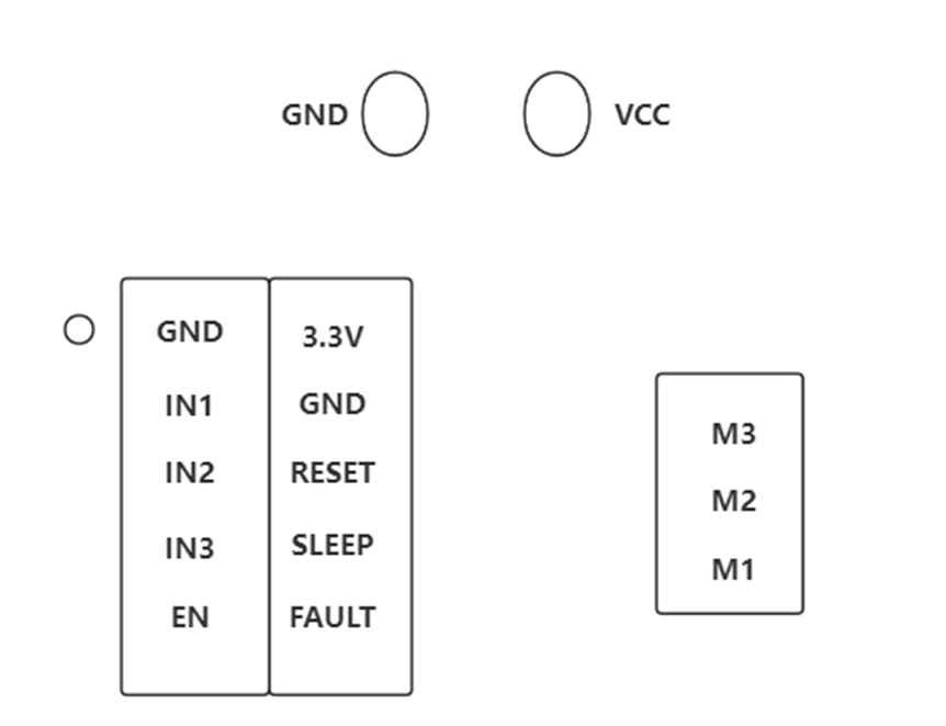
The SimpleFOCmini brushless DC motor driver board simply connects to the control signal and the motor's UVW three-phase wires to achieve open/closed-loop control of the position, speed, and torque of a BLDC motor. It supports SPWM and SVPWM control algorithms, but not the traditional 6-step commutation control algorithm. Using it with a three-phase brushless DC motor allows for quick startup using the SimpleFOC open-source library, and is compatible with development boards such as Arduino, ESP32, and Raspberry Pi.

What is FOC?
Field-Oriented Control (FOC), also known as vector control (VC), is currently one of the most effective methods for efficient control of brushless DC motors (BLDC) and permanent magnet synchronous motors (PMSM). FOC aims to precisely control the magnitude and direction of the magnetic field, resulting in smooth torque, low noise, high efficiency, and fast dynamic response.

Advantages of FOC:

  1. Low-Speed Control
    Due to differences in control principles, brushless ESCs can only control the motor at high speeds and are difficult to control at low speeds. FOC controllers, on the other hand, have no such limitations and can achieve precise control at any speed. 2. Motor Commutation
    For the same reasons as above, sensorless ESCs lack rotor position feedback, making it difficult to achieve forward and reverse commutation. However, FOC drives offer exceptional commutation performance, enabling very smooth forward and reverse switching at maximum speeds. Furthermore, FOC can also provide braking control through energy recovery.
  2. Torque Control
    While conventional ESCs can only control motor speed, FOCs offer closed-loop control of current (torque), speed, and position.
  3. Noise
    FOC drives are significantly quieter than ESCs because conventional ESCs use square wave drive, while FOCs use sinusoidal wave drive.

Features

  • Supports FOC control.
  • Power reverse polarity protection.
  • Compatible with development boards such as Arduino, ESP32, and Raspberry Pi.

Specifications:

  • Input power supply voltage: 8-30V
  • Maximum output current per channel: 2.5A
  • Onboard 3.3L LDO output: Maximum current 10mA, maximum PWM frequency 200kHz
  • Control signal compatibility: 3.3V/5V
  • Dimensions: 26*21.5mm

Board Overview

Pin Function Description
VCC Positive input power Input power 8-30V
GND Negative input power
IN1 Channel 1 input When IN1 is high, M1 is also high; when IN1 is low, M1 is also low
IN2 Channel 1 input When IN2 is high, M2 is also high; when IN2 is low, M2 is also low
IN3 Channel 1 input When IN3 is high, M3 is also high; when IN3 is low, M3 is also low
EN Enable input Simultaneously controls the enable of Channels 1, 2, and 3. Input is valid when high
3.3V 3.3V power supply 3.3V power supply output, maximum output current 10mA
RESET Reset input Sets the chip to summer position and disables the output. Active low
SLEEP Low-power mode Low-power sleep mode, active low
FAULT Fault signal output Outputs protection signals for overtemperature and overcurrent, active low
M1 Output channel 1 Output terminal, follows the IN1 signal, and the output amplitude is the power supply voltage
M2 Output channel 2 Output terminal, follows the IN2 signal, and the output amplitude is the power supply voltage
M3 Output channel 3 Output terminal, follows the IN3 signal, and the output amplitude is the power supply voltage

Dimensional Drawing

Tutorial

Requirements

  • Hardware

  • Software

    • Arduino IDE
    • Download the Arduino_FOC library. This library includes open- and closed-loop control of the position, speed, and torque of a BLDC motor. It supports both the Arduino and ESP32 development boards. You need to adjust the parameters in the code based on the motor parameters.

Connection Diagram

Sample Code

/**
*
* Position/angle motion control example
* Steps:
* 1) Configure the motor and magnetic sensor
* 2) Run the code
* 3) Set the target angle (in radians) from serial terminal
*
*/
#include <SimpleFOC.h> // Be sure to load this library

MagneticSensorI2C sensor = MagneticSensorI2C(AS5600_I2C); // Using I2C communication, connect the SDA and SCL pins of AS5600 to the corresponding SDA and SCL pins of ESP32. There is no need to define the pins. If you want to use other pins, you can do so, but you need to redefine them.

// BLDC motor & driver instance
BLDCMotor motor = BLDCMotor(11); // The number of pole pairs of 2804 and 2208 motors is 7, and the number of pole pairs of 4015 motors is 11
BLDCDriver3PWM driver = BLDCDriver3PWM(9,10,11,8); //PWM pins are 9, 10, and 11, and the enable pin is 8. The wiring of the FOC board and the development board must correspond.

float target_angle = 0; //Define the angle variable, which can also be torque or speed.
//Instantiate the commander
Commander command = Commander(Serial); //Send command via the serial port
void doTarget(char* cmd) { command.scalar(&target_angle, cmd); }

void setup() { //Initialization

// Initialize magnetic sensor hardware
sensor.init(); //Sensor initialization
// Link the motor to the sensor
motor.linkSensor(&sensor); //Motor to sensor connection

// Driver configuration
// Power supply voltage [V]
driver.voltage_power_supply = 12; //Power supply voltage connected to the driver
driver.init(); //Driver initialization
// Link the motor and the driver
motor.linkDriver(&driver); // Connect the motor to the driver

// Choose FOC modulation (optional)
motor.foc_modulation = FOCModulationType::SpaceVectorPWM; // Use PWM drive

// Set the motion control loop to be used
motor.controller = MotionControlType::angle; // Angle mode

// Velocity PI controller parameters
motor.PID_velocity.P = 0.05f; // Velocity P value. This value should not be too large, otherwise it will cause jitter.
motor.PID_velocity.I = 0.02; // A larger value will slow down the response.
motor.PID_velocity.D = 0;
// Maximum voltage to be set to the motor
motor.voltage_limit = 6; // Limit the maximum voltage. This value is generally half the supply voltage.

// Velocity low-pass filtering time constant
// The lower the less filtered value
motor.LPF_velocity.Tf = 0.01f; // Filtering

// Angle P controller
motor.P_angle.P = 20; // P value for position PID control
// Maximum velocity of the position control
motor.velocity_limit = 15; // Maximum velocity limit, radians/second

// Use monitoring with serial
Serial.begin(115200); // Open the serial port
// Comment out if not needed
motor.useMonitoring(Serial); //

// Initialize motor
motor.init(); // Initialize the motor
// Align sensor and start FOC
motor.initFOC(); // Align sensor and start FOC

// Add target command T
command.add('T', doTarget, "target angle"); // Send the position via the serial port T command. For example, T6.28 means the motor rotates 6.28 radians, or 1 revolution.

Serial.println(F("Motor ready."));
Serial.println(F("Set the target angle using serial terminal:"));
_delay(1000);
}

void loop() {
motor.loopFOC(); // Start, apply power

move(target_angle); // Move to target position

command.run(); // Monitor input commands
}

Expected Results

Press the reset button on the development board, the motor will calibrate its position, then input "T6.28" through the serial monitor, the motor will rotate one circle

FAQ

For any questions, advice or cool ideas to share, please visit the DFRobot Forum.

More Documents

Buy Link