Introduction
Get this low-power current sensor to monitor your project every second for saving energy or protecting circuit!
This fully integrated Hall Effect-based linear SC780 current sensor gives precise measurement for both AC and DC currents up to 50A. The thickness of the copper conductor allows survival of the device at high over-current conditions.
The SC780 can output an analog voltage signal that varies linearly with sensed current.
The input and output are designed as through-hole vias and slots, which allow for soldering thick electrical wires and T-shaped connectors. The polarity of the input power is clearly labeled on the board so users can conveniently solder wires or use metal alligator clips to make electrical connection.
The current sensor features enhanced heat dissipation and circuit-protection functions, which typically can be applied to scenarios such as motor control, load detection & management, aeromodelling and robot over-current detection.
Specification
- Operating Voltage: 5V
- Signal Type: analog
- Withstand Voltage in Measuring: 50V(AC) / 120V(DC)
- Current Measurement Range: -50A to 50A
- Signal Bandwidth: 120kHz
- Response Time: 4.6μs
- Operating Temperature: -40℃ to 125℃
- Dimension: 32×42mm/1.26×1.65"
PinOut
Tutorial
This tutorial is going to test DC and AC current. The result of AC current is its effective value, i.e. the same as an Ammeter reading.
Connection Diagram
⚠DANGER: This diagram can also be applied to AC current connection. But notice that the module should be cascaded on one electric wire ( +/- ). If you connect it to two electric wires in parallel, you will short the circuit , which is dangerous.
Signal Convert

- I: Current, in A
- Uout: Voltage on the OUT pin, in V
Note: If I is calculated as a negative number, it means that the current flows from OUT to IN of the module.
DC load
Sketch
/*
50A Current Sensor(DC)(SKU:SEN0098) Sample Code
This code shows you how to get raw datas from the sensor through Arduino and
convert the raw datas to the value of the current according to the datasheet;

Smoothing algorithm (http://www.arduino.cc/en/Tutorial/Smoothing) is used to
make the outputting current value more reliable;

Created 27 December 2011 @Barry Machine @www.dfrobot.com
*/

const int numReadings = 30;
float readings[numReadings];      // the readings from the analog input
int index = 0;                  // the index of the current reading
float total = 0;                  // the running total
float average = 0;                // the average

float currentValue = 0;

void setup()
{
  Serial.begin(115200);
  for (int thisReading = 0; thisReading < numReadings; thisReading  )
    readings[thisReading] = 0;
}
void loop()
{
    total= total - readings[index];
    readings[index] = analogRead(0); //Raw data reading
//Data processing:510-raw data from analogRead when the input is 0;
// 5-5v; the first 0.04-0.04V/A(sensitivity); the second 0.04-offset val;
    readings[index] = (readings[index]-512)*5/1024/0.04-0.04;

    total= total   readings[index];
    index = index   1;
    if (index >= numReadings)
      index = 0;
    average = total/numReadings;   //Smoothing algorithm (http://www.arduino.cc/en/Tutorial/Smoothing)
    currentValue= average;
    Serial.println(currentValue);
    delay(10);
}
Result
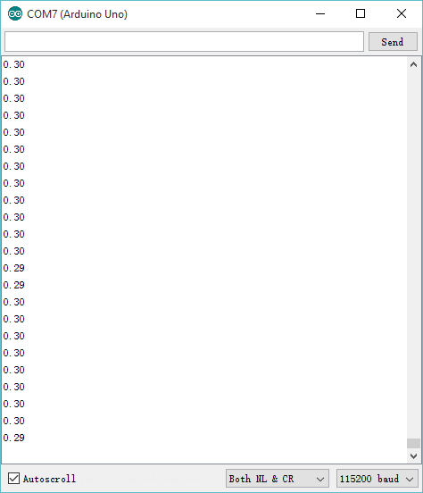
After uploading the sample sketch, open the serial monitor to monitor your results. You may find that when the current is 0A, the reading is not 0A. In this case, you need to revise the code for some small calibrations as the steps below:
1 Check the initial current value when the input is 0A:

2 Caculate the initial current value:
-0.34 = -0.04 - ( 0.30 );
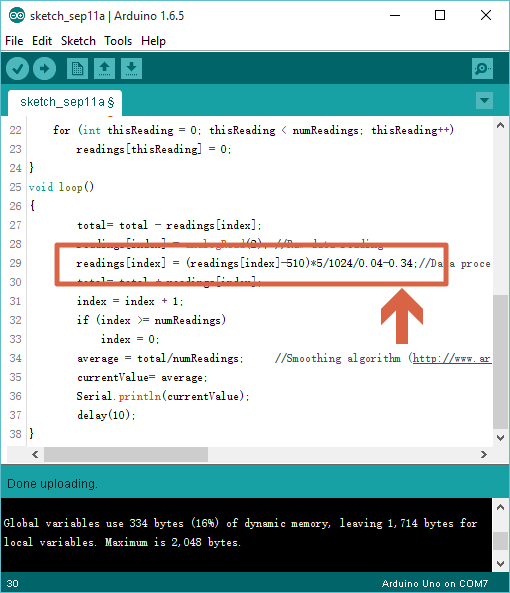
3 Revise the sample sketch:
readings[index] = (readings[index]-510)*5/1024/0.04-0.34;//

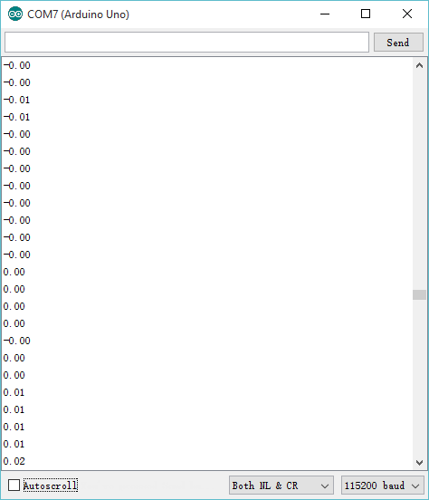
4 Upload your new sketch again, then you will find the readings are around 0A, if not, please do the steps above several times to make it.

5 As shown above, it can be applied to detect the current value accurately, and output analog voltage signals.
AC Load
Sketch
float reading = 0;
float currentValue = 0;

void setup(){
  Serial.begin(115200);
}
void loop() {
  reading = analogRead(*); //Raw data reading
  currentValue = (reading - 510) * 5 / 1024 / 0.04 - 0.34;
  Serial.println(currentValue);
  delay(2);
}
Result of AC current
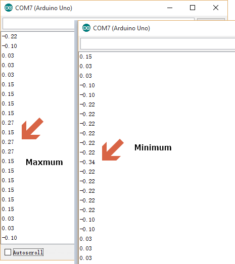
I tested with a lamp @220V~, and got the result shown below:

Since AC current here is a Sine wave, you want to focus on the amplitude of your waveform. You can read the extreme data which are the maxmum value 0.27 and the minimum value -0.34, and use the maxmum absolute value one as the ( Effective) AC current. In this case it is 0.34
FAQ
For any question/advice/cool idea to share, please visit DFRobot Forum