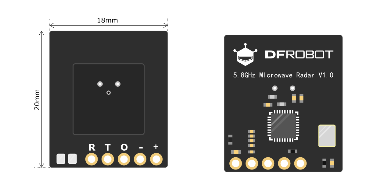
5.8GHZ Microwave Radar Motion Module Wiki - DFRobot

Introduction

This microwave sensor is a microwave module that can transmit the electromagnetic wave of 5.8GHz. It can detect the difference between the transmitted wave and reflection wave to judge whether there is an object moving in the detection area.
Different from the traditional sensors that can only judge human presence by detecting big body movements, this microwave sensor can perform well in detecting micro movements like breathing so as to determine human presence even if the person is sitting or sleeping. The detected result can be output through the serial port or high/low level of the I/O port.
Featuring high reliability and sensitivity, strong anti-interference, it is small and easy to integrate, which can be widely used in fields that require motion detection, such as lighting, security, home, home appliances, hotels, garages, buildings, traffic, etc.

Specification


Interface Definition

Name Description
R Sensor serial receive
T Sensor serial transmit
O Output control signal
- GND
+ VCC

Installation Method & Detection Range

The sensor is strict on the installation method, improper installation will affect the performance and function of the sensor. Commonly-used installation methods for modules include top installation, bottom installation, horizontal installation and downward tilt installation

Top installation

Area A: detect stationary states like standing still, sleeping, sitting still, etc.
Area B: detect small movements (turning head sideways, waving hands, raising hands, slight body movement, turning pages of a book, slight tilting to the left, to the right, forward or backward, etc.)

top


Wall Installation

Area A: detect stationary states like standing still, sleeping, sitting still, etc.
Area B: detect small movements (turning head sideways, waving hands, raising hands, slight body movement, turning pages of a book, slight tilting to the left, to the right, forward or backward, etc.)
Area C: detect sports movements (walking, trotting, running, running in circles, high jump, etc.)


Note: The test proved that the radius is related to many factors such as mounting environment, human body type, relative angle, the amplitude of the specific movements, etc. The parameters above are the test results using pure modules, and the descriptions like small movements and sports movements are all qualitative descriptions instead of quantitative ones, so they are for reference only, and subject to practice if any difference.

Precautions

Tutorial

Requirements

Connection Diagram

Main Function List

/**
   @brief Init function

   @return true Success
   @return false Error
*/
bool begin();

/**
   @brief Read whether the sensor detects the target

   @return true yes
   @return false no
*/
bool readPresenceDetection();

/**
   @brief Configure detection distance

   @param distance detection distance, 0~11m, default to be 6m
*/
void detRangeCfg(int distance);

/**
   @brief Configure detection sensitivity

   @param sensitivity detection sensitivity, 0~9, the larger the value, the higher the sensitivity, default to be 7
*/
void setSensitivity(int sensitivity);

/**
   @brief Configure output delay time

   @param par1 delay acknowledgement; the target is detected, after lasting for par1 time, output valid signal of the target. Value range: 0~100, unit second, the default is 1 second
               For scenarios that don't require high detection response speed, it is recommended to be not less than 1 second, which can largely reduce false positive rate

   @param par2 delay disappearance; no target is detected, after lasting for par2 time, output invalid target signal, value range: 1~1500, unit second, the default is 15 seconds
*/
void outputLatency(int par1, int par2);

/**
   @brief Configure output control signal interface polarity

   @param voltage true Output high level when there is a target, and output low when no target (default status), false output low level when there is a target, and output high when no target
*/
void setGpioMode(bool voltage);

/**
   @brief Restore factory settings

*/
void factoryReset ( void );

Sample Code

Copy and paste the following code into your Arduino IDE and upload it.

#include "DFRobot_Microwave_Radar_Module.h"

#if (defined(ARDUINO_AVR_UNO) || defined(ESP8266))   // Use soft serial port
SoftwareSerial softSerial(/*rx =*/4, /*tx =*/5);
DFRobot_Microwave_Radar_Module Sensor(/*softSerial =*/&softSerial);
#elif defined(ESP32)   // use hard serial port of the pin with remapping function : Serial1
DFRobot_Microwave_Radar_Module Sensor(/*hardSerial =*/&Serial1, /*rx =*/D3, /*tx =*/D2);
#else   // use hard serial port : Serial1
DFRobot_Microwave_Radar_Module Sensor(/*hardSerial =*/&Serial1);
#endif

int ledPin = 13;

void setup()
{
  Serial.begin(115200);

  //Initialize sensor
  while ( !( Sensor.begin() ) ) {
    Serial.println("Communication with device failed, please check connection");
    delay(3000);
  }
  Serial.println("Begin ok!");

  pinMode(ledPin, OUTPUT);

  /**
     @brief Restore factory settings
  */
  Sensor.factoryReset();

  /**
     @brief Configure detection distance, 0~11m, the default is 6m
  */
  Sensor.detRangeCfg(6);

  /**
     @brief Configure detection sensitivity, 0~9, the larger the value, the higher the sensitivity, default to be 7
  */
  Sensor.setSensitivity(3);

  /**
     @brief Configure output delay time
  */
  Sensor.outputLatency(1, 15);

  /**
     @brief Configure output control signal interface polarity
  */
  Sensor.setGpioMode(1);
}

void loop()
{
  int val = Sensor.readPresenceDetection();
  digitalWrite(ledPin, val);
  Serial.println(val);
}

Result

FAQ

For any questions, advice or cool ideas to share, please visit the DFRobot Forum.

More Documents

Datasheet

DFshopping_car1.png Get 5.8G Microwave Radar Module from DFRobot Store or DFRobot Distributor.

Turn to the Top