1. Introduction
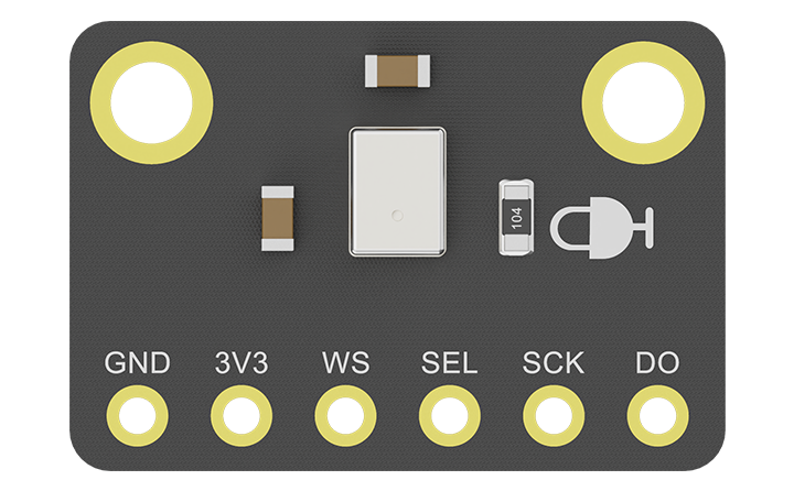
This digital I2S MEMS Microphone works well with microcontrollers with I2S audio outputs like ESP32. Compared with traditional analog ones, this microphone features low noise, high sensitivity & reliability, and other excellent performances, which make it applicable to projects like voice recognition, recording, AI learning, Bluetooth audio transmission, and so on.
This module uses surface mount MEMS I2S microphone sensor with top port, no components at the bottom, which can be embedded into various applications conveniently. Besides, DFRobot provides users with Arduino library for this product to allow them easily get started on ESP32.
2. Features
- Small in size
- Low power consumption & high performance
- I2S digital output with low noise
- MEMS sensor with high reliability
- Provides Arduino library for working on ESP32
3. Application
- Voice recognition
- AI learning
- Recording
- Bluetooth audio streaming
- Smart home audio projects
4. Pinout

| Name | Function | Description |
|---|---|---|
| 3V3 | Power + | DC 3.3V |
| GND | Power - | Negative pole of power supply |
| SCK | I2S clock | Serial data clock for I2S interface |
| SEL | Select left or right channel | Left/Right Channel Select. When set low, the microphone outputs its signal in the left channel of the I²S frame; when set high, the microphone outputs its signal in the right channel |
| WS | Data field select | Select the data of the left or right channel, connect to WS of I2S interface |
| DO | Data output | Serial data output of the I2S microphone |
5. Specification
- Operating Voltage: DC 3.3V
- Microphone Packaging Process: MEMS
- Direction: Omnidirectional
- Data Port: I2S
- Sound Pressure Level: 140dB
- Signal-to-noise Ratio: 59dB
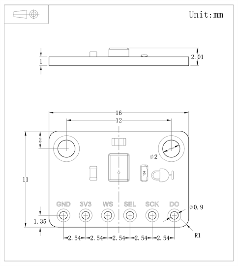
- Dimension: 11mm×16mm/0.43×0.63"
6. Dimension

7. ESP32 Tutorial
7.1 Microphone Input Test
7.1.1 Hardware Requirements
- FireBeetle 2 ESP32-E IoT Microcontroller (SKU: DFR0654) × 1
- Fermion: I2S MEMS Microphone (SKU: SEN0526) × 1
- M-M/F-M/F-F Jumper wires
7.1.2 Software Requirements
- Arduino IDE
- Install SDK: refer to the wiki of FireBeetle 2 ESP32-E IoT Microcontroller for SDK installation tutorial
- Download and install the Arduino Library. (About how to install the library?)
7.1.3 Connection Diagram

Pin Connections:
I2S Microphone: VCC (to) ESP32-E Microcontroller: 3V3;
I2S Microphone: GND (to) ESP32-E Microcontroller: GND;
I2S Microphone: SEL (to) ESP32-E Microcontroller: 4/D12;
I2S Microphone: DO (to) ESP32-E Microcontroller: 26/D3;
I2S Microphone: SCK (to) ESP32-E Microcontroller: 25/D2;
I2S Microphone: WS (to) ESP32-E Microcontroller: 16/D11;
7.1.4 Sample Code
Function: The microphone reads data of left channel and prints the data.
#include "DFrobot_MSM261.h"

#define SAMPLE_RATE     (44100)
#define I2S_SCK_IO      (25)
#define I2S_WS_IO       (16)
#define I2S_DI_IO       (26)
#define DATA_BIT        (16)
#define MODE_PIN        (4)
DFRobot_Microphone microphone(I2S_SCK_IO, I2S_WS_IO, I2S_DI_IO);
char i2sReadrawBuff[100];
void setup() {
  Serial.begin(115200);//Serial rate 115200
  pinMode(MODE_PIN,OUTPUT);
  digitalWrite(MODE_PIN,LOW);//Configure the microphone as receiving data of left channel
  while(microphone.begin(SAMPLE_RATE, DATA_BIT) != 0){
      Serial.println(" I2S init failed");//Init failed
  }
  Serial.println("I2S init success");//Init succeeded
}

void loop() {
  microphone.read(i2sReadrawBuff,100);
  //Output data of left channel
  Serial.println((int16_t)(i2sReadrawBuff[0]|i2sReadrawBuff[1]<<8));
  delay(100);
}
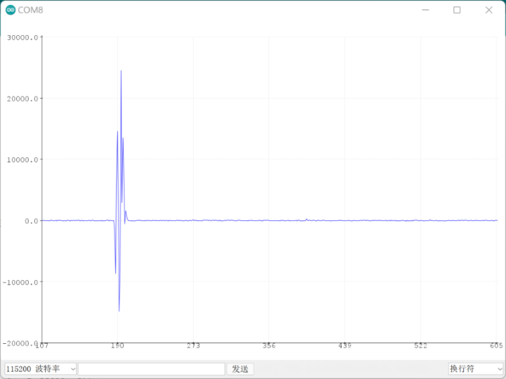
Result
Blow into the microphone, and the corresponding peak & trough of the wave can be seen in the serial monitor.

7.2 Microphone Recording Test
7.2.1 Hardware Requirements
- FireBeetle 2 ESP32-E IoT Microcontroller (SKU: DFR0654) × 1
- MicroSD Module (SKU: DFR0229) × 1
- SD/MicroSD Memory Card (SKU: FIT0394) × 1
- Kawau C289 TF Card/MicroSD Card Reader × 1
- Fermion: I2S MEMS Microphone (SKU: SEN0526) × 1
- M-M/F-M/F-F Jumper wires
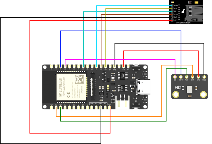
7.2.2 Connection Diagram

Pin Connections:
I2S Microphone: VCC (to) ESP32-E Microcontroller: 3V3;
I2S Microphone: GND (to) ESP32-E Microcontroller: GND;
I2S Microphone: SEL (to) ESP32-E Microcontroller: 4/D12;
I2S Microphone: DO (to) ESP32-E Microcontroller: 26/D3;
I2S Microphone: SCK (to) ESP32-E Microcontroller: 25/D2;
I2S Microphone: WS (to) ESP32-E Microcontroller: 16/D11;
MicroSD Module: +5V (to) ESP32-E Microcontroller: VCC;
MicroSD Module: GND (to) ESP32-E Microcontroller: GND;
MicroSD Module: MOSI (to) ESP32-E Microcontroller: 23/MOSI;
MicroSD Module: SS (to) ESP32-E Microcontroller: 2/D9;
MicroSD Module: SCK (to) ESP32-E Microcontroller: 18/SCK;
MicroSD Module: MISO (to) ESP32-E Microcontroller: 19/MISO;
7.2.3 Sample Code
Fucntion: This sample shows how to record a 20s audio with the parameter of 16bit & 44.1kHz and save it to the SD card as a WAVE file.
Note: Use the parameter of 16bit & 44.1kHz (in the format of a CD)
The higher the sampling frequency, the better the sound quality and the larger the data size. The commonly used frequencies include 11.025kHz, 22.05kHZ, 44.1kHz, 48kHz and 96kHz.
The bigger the bit depth, the better the sound quality and the larger the data size. The commonly used bit depth includes 8-bit, 16-bit, 24-bit and 32-bit.
#include "DFrobot_MSM261.h"
#include "SPI.h"
#include <SD.h>
#include <FS.h>
#define SAMPLE_RATE     (44100) //Change sampling frequency
#define I2S_SCK_IO      (25)
#define I2S_WS_IO       (16)
#define I2S_DI_IO       (26)
#define DATA_BIT        (16) //Change bit depth
#define MODE_PIN        (4)

const int record_time = 20;  // Sampling time
const char filename[] = "/sound.wav";//The name of the saved file

const int headerSize = 44;
const int byteRate = 176400;//The number of the byte sampled per second, calculation formula: sampling rate × the number of sound channels × data bit/8
const int waveDataSize = record_time * byteRate;//10-second sampled byte
const int numCommunicationData = 512;//The amount of data collected every time
byte header[headerSize];//The file header of the WAVE file
char communicationData[numCommunicationData];

DFRobot_Microphone microphone(I2S_SCK_IO, I2S_WS_IO, I2S_DI_IO);
File file;

void setup() {
  Serial.begin(115200);
  pinMode(MODE_PIN,OUTPUT);
  digitalWrite(MODE_PIN,LOW);//Configure the microphone as receiving data of left channel
  //digitalWrite(MODE_PIN,HIGH);//Configure the microphone as receiving data of right channel
  while(microphone.begin(SAMPLE_RATE, DATA_BIT) != 0){
      Serial.println(" I2S init failed");
  }
  Serial.println("I2S init success");
  if (!SD.begin(2)) Serial.println("SD begin failed");
    while(!SD.begin(2)){
      Serial.print(".");
      delay(500);
    }

  microphone.createWavHeader(header, waveDataSize,44100,2,byteRate,4);
  SD.remove(filename);
  //Open the file, create one if there is no file
  file = SD.open(filename, FILE_WRITE);
  if (!file) return;
  //Write the header of the wave file into the file
  file.write(header, headerSize);
  Serial.println("start");
  for (int j = 0; j < waveDataSize/numCommunicationData; ++j) {
    microphone.read(communicationData, numCommunicationData);
    for(uint32_t i = 0;i < (numCommunicationData>>2);i++){
      communicationData[(i<<2)] = 0;
      communicationData[(i<<2)+1] = 0;
      //communicationData[(i<<2)+2] = 0;
      //communicationData[(i<<2)+3] = 0;
    }
    file.write((uint8_t*)communicationData, numCommunicationData);
  }
  file.close();
  Serial.println("finish");
}

void loop() {
}
Result
Burn the codes, open the serial port, then start to record when "start" appears, and finish it when "finish" appears.

Check if there is a recording file in the SD card.

8. API Function
 /**
   * @fn begin
   * @brief Initialize the device
   * @param baudRate Communication rate
   * @param bit the number of data bit
   * @return Return init status
   */
  uint8_t begin(uint16_t baudRate,uint8_t bit)

  /**
   * @brief Get the data returned from microphone
   * @param buffer Get data buffer
   * @param len    Get data length
   * @return Return the obtained data length
   */
  uint32_t read(char *buffer,size_t len)

  /**
   * @brief Construct the header for the WAVE file
   * @param header Construct the WAVE file
   * @param totalDataLen The length of the data to be written
   * @param longSampleRate Sampling frequency
   * @param channels The number of sound channels
   * @param byteRate Byte rate, calculation formula: sampling rate × the number of sound channels × data bit/8
   * @param blockAlign Block-aligning way, calculation formula: the number of sound channels × data bit/8
   */
    void createWavHeader(byte* header, int totalDataLen, int longSampleRate, uint8_t channels, int byteRate, uint8_t blockAlign)

  /**
   * @brief Initialize bluetooth & a2dp
   * @param name  Bluetooth Name
   * @param callback a2dp sends data callback function
   * @param volume Volume
   */
  bool begin(const char* name, esp_a2d_source_data_cb_t callback,uint8_t volume);
9. More Documents
SEN0526 Schematics Diagram.pdf
FAQ
For any questions, advice or cool ideas to share, please visit the DFRobot Forum.
