Introduction
The UV sensor uses a photoelectric detector to receive UV light wave electrical signals, and can measure the UV intensity and index values in the wavelength range of 290-390nm. The internal circuit uses imported industrial-grade microprocessor chips and high-precision UV sensors to ensure the excellent reliability and stability of the product.
The UV sensor uses the standard Modbus-RTU 485 communication protocol and DC5-30V wide voltage power supply. It can be used with the TTL to RS485 expansion board (DFR0259) or Gravity: Active Isolated RS485 to UART Signal Adapter Module (DFR0845) to read the UV intensity and index values on the Arduino UNO R3, quickly build a test environment, and the wiring method is simple and easy to use. The UV sensor has an IP67 protection level and is made of metal aluminum shell. It is widely used in environmental monitoring, health protection monitoring, crop growth monitoring, photovoltaic systems, laboratory research and other fields.
What is UV?
Ultraviolet (UV) is an invisible electromagnetic wave with a shorter wavelength than visible light but longer than X-rays. The wavelength of UV light usually ranges from 10 nanometers (nm) to 400 nanometers. UV light can be divided into three main types according to its wavelength: UVA, UVB and UVC.
Biological effects:
- UVA (320-400nm): the most common and the most penetrating, can penetrate the dermis of the skin, and long-term exposure may cause skin aging, wrinkles and skin cancer.
- UVB (280-320nm): less penetrating, mainly acts on the epidermis of the skin, is the main cause of sunburn, and is an important source of synthetic vitamin D, but can also cause skin cancer.
- UVC (100-280nm): has the strongest bactericidal effect, is usually absorbed by the earth's atmosphere and fails to reach the surface. However, artificial UVC light sources (such as disinfection lamps) are widely used in industry and medicine.
Role in nature:
- Synthetic vitamin D: UV light helps the skin synthesize vitamin D, which is essential for bone health.
- Ecosystem: UV light affects the photosynthesis of plants and the growth cycle of plants, and plays an important role in ecological balance.
Hazards of UV rays:
- Skin damage: UV rays can damage the DNA of skin cells and increase the risk of skin cancer.
- Eye damage: Long-term exposure to UV rays can cause eye diseases such as cataracts and keratitis.
- Immune system suppression: Excessive UV rays may affect the normal function of the immune system.
UV Index range and health recommendations
1. 0-2: Low risk
- Health impact: For most people, the health impact of UV radiation is very small.
- Recommendation: Even in such low-risk situations, some basic protective measures can be taken, such as wearing sunglasses.
2. 3-5: Moderate risk
- Health impact: The health impact of UV radiation begins to become significant, especially under long-term exposure.
- Recommendation: When doing outdoor activities, it is recommended to take some protective measures, such as using sunscreen, wearing sun-shielding clothing and wearing sunglasses.
####3. 6-7: High Risk
- Health effects: UV radiation has a significant impact on health and may cause sunburn and eye damage.
- Recommendation: Avoid prolonged exposure to the sun during midday hours (10:00AM to 4:00PM). Wear protective clothing, high SPF sunscreen, and sunglasses.
####4. 8-10: Very High Risk
- Health effects: UV radiation has a significant impact on health and the risk of sunburn is high.
- Recommendation: Avoid prolonged activities in the sun as much as possible. Take comprehensive protective measures, including wearing sun-protective clothing, high SPF sunscreen, hats and sunglasses, especially during periods of strong sunlight.
####5. 11+: Very High Risk
- Health effects: UV radiation is extremely strong and can cause severe sunburn in a short period of time.
- Recommendation: Avoid activities in the sun as much as possible, especially during midday hours. Take all possible protective measures and stay in the shade as much as possible.
Features
- DC 5~30V wide voltage power supply
- Can directly output UV intensity value and index value
- Adopt high-precision photosensitive element, high absorption in the full spectrum range
- Equipped with level gauge and adjustment hand wheel, convenient for on-site adjustment
- Adopt RS485 interface, standard Modbus-RTU protocol
- Metal aluminum shell material, IP67 protection level
Applications
- Environmental monitoring
- Health protection monitoring
- Crop growth monitoring
- Photovoltaic systems
- Laboratory research
Specifications:
- Supply voltage: DC5~30V
- Working current: <10mA
- Output mode: RS485
- UV intensity measurement range: 0~15mW/cm²
- Resolution: 0.01mW/cm²
- Accuracy: ±10%FS (@365nm, 60%RH, 25°C)
- UV index measurement range: 0-15
- Wavelength range: 290-390nm
- Response time: 0.2s
- Working temperature: -25°C~+60°C
- Protection level: IP67
- Sensor cable length: 20cm
- Adapter cable length: 70cm
Board Overview
| Num | Label | Description |
|---|---|---|
| Brown line | VCC | Power input positive pole, DC5-30V power supply |
| Black line | GND | Power ground wire |
| Yellow line | 485-A | RS485 data line A |
| Blue line | 485-B | RS485 data line B |
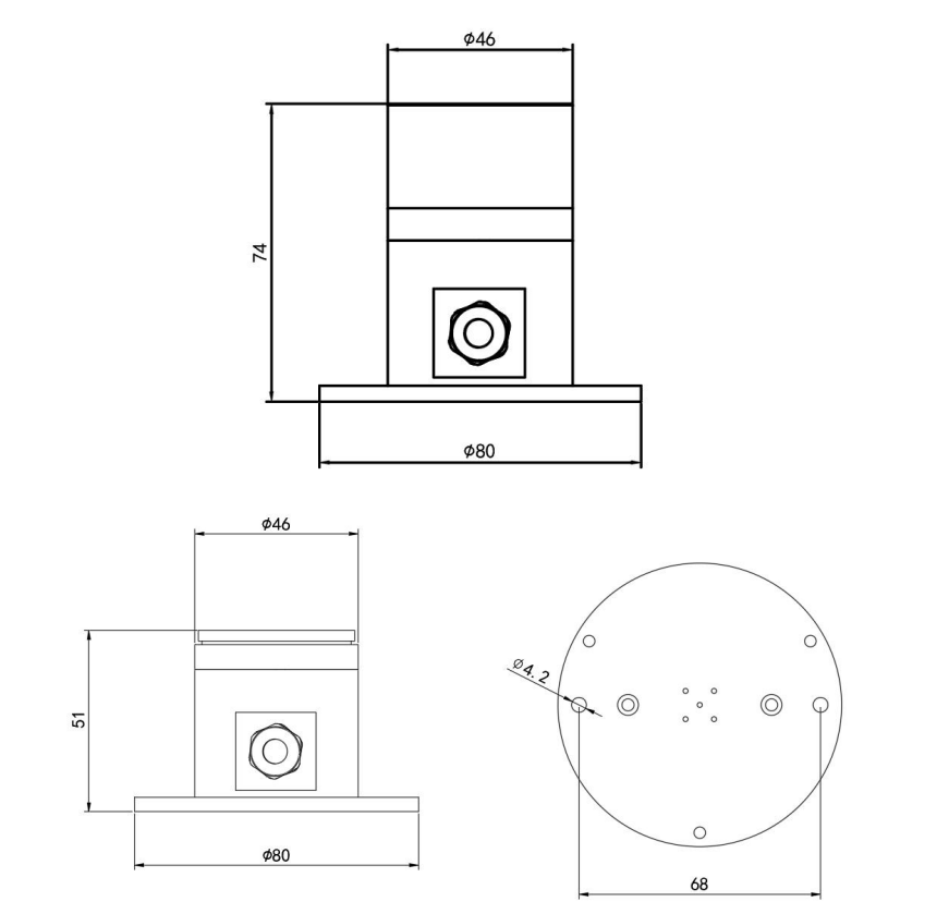
Dimensional Drawing

Communication Protocol
1. Basic communication parameters
| Interface | Encoding | Data bits | Parity bits | Stop bits | Error checking | Baud rate |
|---|---|---|---|---|---|---|
| RS485 | 8-bit binary | 8 | None | 1 | CRC | 2400bit/s, 4800bit/s, 9600 bit/s configurable, default 4800bit/s |
2. Data frame format definition
Using Modbus-RTU communication protocol, the format is as follows:
Initial structure ≥4 bytes of time
Address code = 1 byte
Function code = 1 byte
Data area = N bytes
Error check = 16-bit CRC code
End structure ≥4 bytes of time
Address code: The address of the sensor, which is unique in the communication network (factory default 0x01).
Function code: The function indication of the command sent by the host. This sensor reads the register function code 0x03 and writes the register function code 0x06
Data area: The data area is the specific communication data. Note that the high byte of 16-bit data is in front!
CRC code: A two-byte check code.
Host inquiry frame structure:
| Address code | Function code | Register start address | Register length | Check code low bit | Check code high bit |
|---|---|---|---|---|---|
| 1byte | 1byte | 2byte | 2byte | 1byte | 1byte |
Slave response frame structure:
| Address code | Function code | Number of valid bytes | Data area 1 | Data area 2 | Nth data area | Check code |
|---|---|---|---|---|---|---|
| 1byte | 1byte | 1byte | 2byte | 2byte | 2byte | 2byte |
Register address
| Register address | Content | Operation | Range and definition |
|---|---|---|---|
| 0000H | UV intensity | Read only | 100 times the actual value |
| 0001H | UV index | Read only | Actual value |
| 0052H | UV intensity deviation | Read and write | 100 times the actual value |
| 07D0H | Device address | Read and write | 1~254 (factory default 1) |
| 07D1H | Device baud rate | Read and write | 0 represents 2400, 1 represents 4800, 2 represents 9600 |
3. Communication protocol example and explanation
3.1. Read the current UV intensity value
Inquiry frame:
| Address code | Function code | Register start address | Register length | Check code low bit | Check code high bit |
|---|---|---|---|---|---|
| 0x01 | 0x03 | 0x00 0x00 | 0x00 0x01 | 0x84 | 0x0A |
Response frame:
| Address code | Function code | Return valid bytes | UV intensity value | Check code low bit | Check code high bit |
|---|---|---|---|---|---|
| 0x01 | 0x03 | 0x02 | 0x01 0x43 | 0xF8 | 0x25 |
Ultraviolet intensity value:
0143 (hexadecimal) = 323=> Ultraviolet intensity = 3.23mW/cm2
3.2, read the current UV index value
Inquiry frame:
| Address code | Function code | Register address | UV index value | Check code low | Check code high |
|---|---|---|---|---|---|
| 0x01 | 0x03 | 0x00 0x01 | 0x00 0x01 | 0xD5 | 0xCA |
Response frame:
| Address code | Function code | Return valid bytes | UV index value | Check code low | Check code high |
|---|---|---|---|---|---|
| 0x01 | 0x03 | 0x02 | 0x00 0x03 | 0xF8 | 0x45 |
UV index:
0003 (hexadecimal) = 3 => UV index = 3
3.3 modify the current address
Inquiry frame: (modify the current address to 0x02)
| Address code | Function code | Register address | Modify value | Check code low position | Check code high position |
|---|---|---|---|---|---|
| 0x01 | 0x06 | 0x07 0xD0 | 0x00 0x02 | 0x08 | 0x86 |
Response frame:
| Address code | Function code | Register address | Modify value | Check code low position | Check code high position |
|---|---|---|---|---|---|
| 0x01 | 0x06 | 0x07 0xD0 | 0x00 0x02 | 0x08 | 0x86 |
3.4 Modify the current baud rate
Inquiry frame: (Modify the current baud rate to 9600)
| Address code | Function code | Register address | Modify value | Check code low bit | Check code high bit |
|---|---|---|---|---|---|
| 0x01 | 0x06 | 0x07 0xD1 | 0x00 0x02 | 0x59 | 0x46 |
Response frame:
| Address code | Function code | Register address | Modify value | Check code low bit | Check code high |
|---|---|---|---|---|---|
| 0x01 | 0x06 | 0x07 0xD1 | 0x00 0x02 | 0x59 | 0x46 |
3.5 Query current address and baud rate
Inquiry frame:
| Address code | Function code | Register address | Data length | Check code low | Check code high |
|---|---|---|---|---|---|
| 0xFF | 0x03 | 0x07 0xD0 | 0x00 0x02 | 0xD1 | 0x58 |
Response frame:
| Address code | Function code | Return valid bytes | Address | Baud rate | Checksum low bit | Checksum high bit |
|---|---|---|---|---|---|---|
| 0x01 | 0x03 | 0x04 | 0x00 0x01 | 0x00 0x01 | 0x6A | 0x33 |
The real address of the device read is 01, and the baud rate is 0x01, that is, 4800.
Tutorial
Requirements
-
Hardware
- DFRduino UNO R3 (or similar) x 1
- Gravity: Active Isolated RS485 to UART Signal Adapter Module x1
- RS485 UV Sensor x1
-
Software
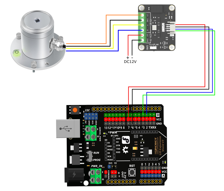
Connection Diagram
If the power of the RS485 device is small and the required current is less than 12V-160mA, the RS485 to UART signal conversion module does not require a 12V external power supply, making wiring more convenient.

Sample Code
#include <SoftwareSerial.h>
SoftwareSerial mySerial(2,3);
uint8_t Com[8] = { 0x01, 0x03, 0x00, 0x00, 0x00, 0x01, 0x84, 0x0A };
uint8_t Com1[8] = { 0x01, 0x03, 0x00, 0x01, 0x00, 0x01, 0xD5, 0xCA };
void setup() {
  Serial.begin(9600);
  mySerial.begin(4800);
}
void loop() {
  float UV = readUV();
  Serial.print("UV = ");
  Serial.print(UV);
  Serial.print(" mW/cm² ");
  uint16_t UVI = readUVI();
  Serial.print("UVI = ");
  Serial.println(UVI);
  delay(1000);
}

float readUV(void) {
  uint8_t Data[10] = { 0 };
  uint8_t ch = 0;
  float data;
  bool flag = 1;
  while (flag) {
    delay(100);
    mySerial.write(Com, 8);
    delay(10);
    if (readN(&ch, 1) == 1) {
      if (ch == 0x01) {
        Data[0] = ch;
        if (readN(&ch, 1) == 1) {
          if (ch == 0x03) {
            Data[1] = ch;
            if (readN(&ch, 1) == 1) {
              if (ch == 0x02) {
                Data[2] = ch;
                if (readN(&Data[3], 4) == 4) {
                  if (CRC16_2(Data, 5) == (Data[5] * 256 + Data[6])) {
                    data= (Data[3] * 256 + Data[4]) / 100.00;
                    flag = 0;
                  }
                }
              }
            }
          }
        }
      }
    }
    mySerial.flush();
  }
  return data;
}

int readUVI(void) {
  uint8_t Data1[10] = { 0 };
  int16_t data1;
  uint8_t ch1 = 0;
  bool flag1 = 1;
  while (flag1) {
    delay(100);
    mySerial.write(Com1, 8);
    delay(10);
    if (readN(&ch1, 1) == 1) {
      if (ch1 == 0x01) {
        Data1[0] = ch1;
        if (readN(&ch1, 1) == 1) {
          if (ch1 == 0x03) {
            Data1[1] = ch1;
            if (readN(&ch1, 1) == 1) {
              if (ch1 == 0x02) {
                Data1[2] = ch1;
                if (readN(&Data1[3], 4) == 4) {
                  if (CRC16_2(Data1, 5) == (Data1[5] * 256 + Data1[6])) {
                    data1 = Data1[3] * 256 + Data1[4];
                    flag1 = 0;
                  }
                }
              }
            }
          }
        }
      }
    }
    mySerial.flush();
  }
  return data1;
}

uint8_t readN(uint8_t *buf, size_t len) {
  size_t offset = 0, left = len;
  int16_t Tineout = 500;
  uint8_t *buffer = buf;
  long curr = millis();
  while (left) {
    if (mySerial.available()) {
      buffer[offset] = mySerial.read();
      offset++;
      left--;
    }
    if (millis() - curr > Tineout) {
      break;
    }
  }
  return offset;
}

unsigned int CRC16_2(unsigned char *buf, int len) {
  unsigned int crc = 0xFFFF;
  for (int pos = 0; pos < len; pos++) {
    crc ^= (unsigned int)buf[pos];
    for (int i = 8; i != 0; i--) {
      if ((crc & 0x0001) != 0) {
        crc >>= 1;
        crc ^= 0xA001;
      } else {
        crc >>= 1;
      }
    }
  }

  crc = ((crc & 0x00ff) << 8) | ((crc & 0xff00) >> 8);
  return crc;
}
Expected Results
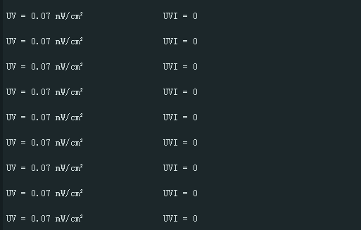
Print the collected UV intensity and index values, which cannot be collected by ordinary indoor light sources.

FAQ
Possible reasons for no output or output errors:
- The sensor is a precision device. Please do not disassemble it by yourself when using it to avoid damage to the product.
- If the reading value is 0, check whether there is a light source and whether the product protective cover is removed.
- The 485 bus is disconnected, or the A and B lines are connected in reverse.
- Check whether the power supply meets the marking.
For any questions, advice or cool ideas to share, please visit the DFRobot Forum.