Introduction
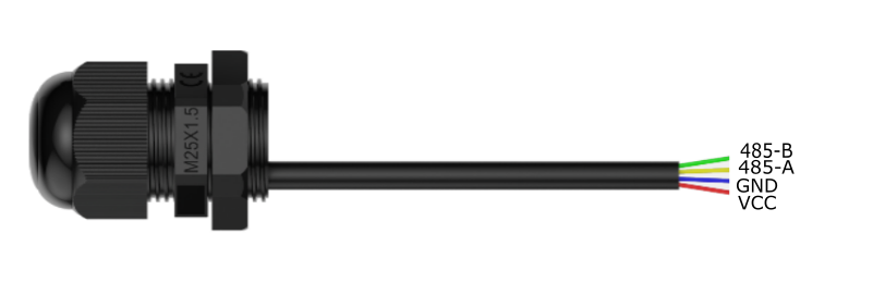
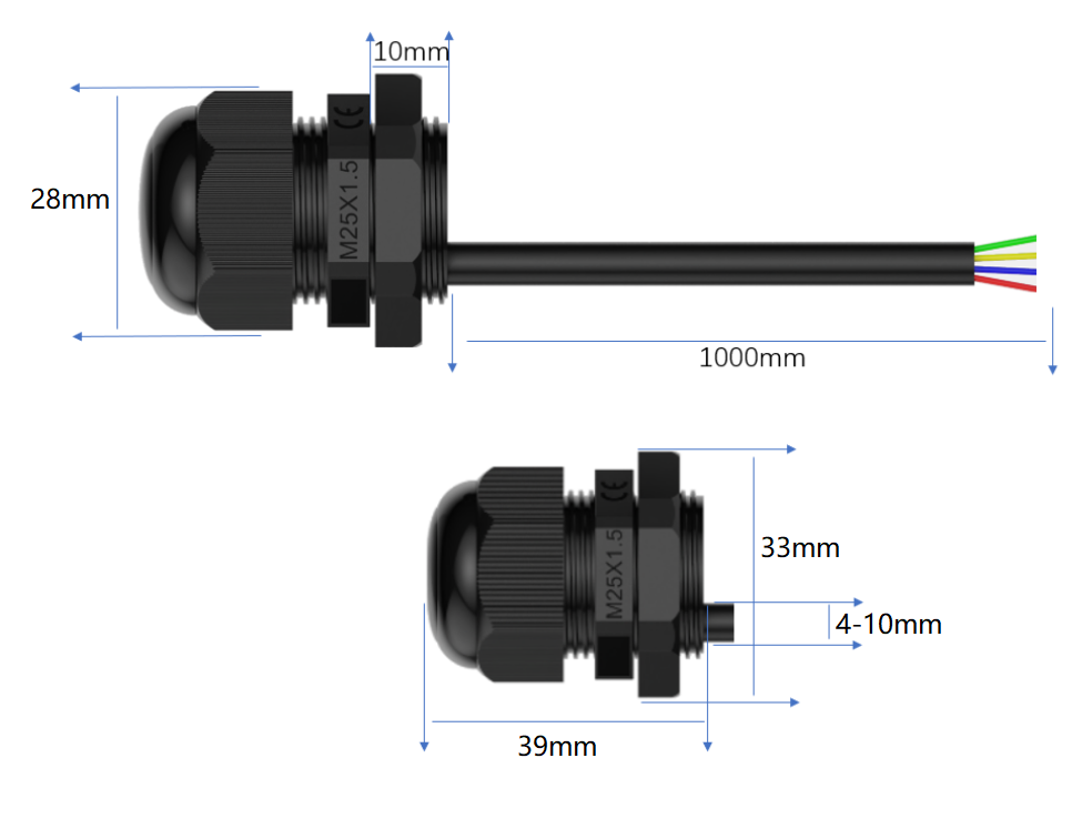
This is a completely waterproof digital ambient light sensor that measures the intensity of light in different environments with a detection range of 0~200Klux. It uses the standard Modbus-RTU 485 communication protocol and a DC5-32V wide voltage power supply. It can be used with the TTL to RS485 expansion board (DFR0259) or the Gravity: Active Isolated RS485 to UART Signal Adapter Module (DFR0845) to read the light value on the Arduino UNO R3, quickly build a test environment, and has a simple wiring method and is easy to use. The ambient light sensor has an IP68 waterproof rating and can be completely immersed in water without damage. It is suitable for various indoor and outdoor harsh environments such as weather stations, vegetable greenhouses, outdoor lighting, flower cultivation, factory workshop lighting, and automotive smart lights.
Brightness data reference:
At night: 0.001-0.02 lx;
Moonlit night: 0.02-0.3 lx;
Cloudy indoor: 5-50 lx;
Cloudy outdoor: 50-500 lx;
Sunny indoor: 100-1000 lx;
Summer noon light: about 10*6 lx;
Illumination when reading books: 50-60 lx;
Standard illumination for home video: 1400 lx;
Features
- Waterproof grade IP68
- DC 5~32V wide voltage power supply
- 0~200Klux wide range measurement range
- RS485 interface, standard Modbus-RTU protocol
Applications
- Weather station
- Vegetable greenhouse
- Outdoor lighting
- Flower cultivation Factory workshop lighting
- Automotive smart lights
Specifications:
- Power supply voltage: DC5~32V
- Working current: <10mA
- Output mode: RS485
- Measurement range: 0~200000Lux
- Resolution: 0.01Lux
- Accuracy: ±5%
- Working temperature: -40°C~+80°C
- Protection level: IP68
- Thread length: 10mm
- Opening size: 25mm
- Wrench size: 33mm
- Cable diameter: 4-10mm
- Line length: 1m
Board Overview

Num | Label | Description |
---|---|---|
Red line | VCC | Power input positive pole, DC5-32V power supply |
Blue line | GND | Power ground wire |
Yellow line | 485-A | RS485 data line A |
Green line | 485-B | RS485 data line B |
Dimensional Drawing

Communication Protocol
1. Basic communication parameters
Interface | Encoding | Data bits | Parity bits | Stop bits | Error checking | Baud rate |
---|---|---|---|---|---|---|
RS485 | 8-bit binary | 8 | None | 1 | CRC | 1200、2400、4800、9600、19200、38400、57600 bit/s configurable, default 9600bit/s |
2. Data frame format definition
Using Modbus-RTU communication protocol, the format is as follows:
Initial structure ≥4 bytes of time
Address code = 1 byte
Function code = 1 byte
Data area = N bytes
Error check = 16-bit CRC code
End structure ≥4 bytes of time
Address code: The address of the sensor, which is unique in the communication network (factory default 0x01).
Function code: The function indication of the command sent by the host. This sensor reads the register function code 0x03 and writes the register function code 0x06
Data area: The data area is the specific communication data. Note that the high byte of 16-bit data is in front!
CRC code: A two-byte check code.
Register address
Register address | Content | Operation | Range and definition |
---|---|---|---|
0002H | High 16-bit data of illumination value | Read-only | Two bytes |
0003H | Low 16-bit data of illumination value | Read-only | Two bytes |
0046H | Illumination acquisition rate | Read-write | Level 1-20 |
0047H | Illumination calibration enable bit | Read-write | 01 Enable illumination calibration function, 00 Disable illumination calibration function |
0048H | Illumination calibration compensation value | Read-write | This value is written with the actual value enlarged by 100 times; for example, if compensation of 1.4 is required, the written value needs to be enlarged by 100 times, that is, 140; Calculation method: (collected illumination value ÷ ambient illumination value) × 100 = compensation value For example: the collected illumination value is 221, the actual ambient illumination is 260, and the calculated compensation value = (221 ÷ 260) × 100 = 85 |
0064H | 16-bit device address | Read and write | Range is (1-254), 255 is the general control command address |
0065H | 16-bit baud rate selection | Read and write | 0-1200, 1-2400, 2-4800, 3-9600, 4-19200, 5-38400, 6-57600 |
0066H | Parity bit | Read and write | 00 no parity, 01 odd parity, 02 even parity |
0067H | Version information | Read only | Level 1-20 |
00E0H | Device soft reset write command | Write only | Level 1-20 |
00F0H | Device factory reset write command | Write only | Level 1-20 |
3. Communication protocol example and explanation
3.1、Read multiple register illumination data instruction
Inquiry frame:
Address code | Function code | Register start address | Register length | Check code low bit | Check code high bit |
---|---|---|---|---|---|
0x01 | 0x03 | 0x00 0x02 | 0x00 0x02 | 0x65 | 0xCB |
Response frame:
Address code | Function code | Return valid bytes | Illumination data high 16 bits | Illumination data low 16 bits | Check code low bit | Check code high bit |
---|---|---|---|---|---|---|
0x01 | 0x03 | 0x04 | 0x00 0x0C | 0xF4 0x73 | 0x3D | 0x15 |
Light value:
00 0C F4 73 (hexadecimal) =849011/1000 =>Light value = 849.011Lux
3.2, Modify the current address
Inquiry frame: (Modify the current address to 0x02)
Address code | Function code | Register address | Modify value | Check code low bit | Check code high bit |
---|---|---|---|---|---|
0x01 | 0x06 | 0x00 0x64 | 0x00 0x02 | 0x49 | 0xD4 |
Response frame:
Address code | Function code | Register address | Modify value | Checksum low bit | Checksum high bit |
---|---|---|---|---|---|
0x01 | 0x06 | 0x00 0x64 | 0x00 0x02 | 0x49 | 0xD4 |
3.3, Modify address, baud rate
Inquiry frame: (Modify address to 0x01, baud rate to 9600)
After modifying the address or baud rate, the sensor needs to be powered off and reconnected
Address code | Function code | Register start address | Register length | Modify address | Modify baud rate | Parity check | Checksum low bit | Checksum high bit |
---|---|---|---|---|---|---|---|---|
0x01 | 0x10 | 0x00 0x64 | 0x00 0x03 | 0x00 0x01 | 0x00 0x03 | 0x00 0x00 | 0xA9 | 0x03 |
Response frame:
Address code | Function code | Register start address | Register length | Modify address | Modify baud rate | Checksum low bit | Checksum high bit |
---|---|---|---|---|---|---|---|
0x01 | 0x10 | 0x00 0x64 | 0x00 0x03 | 0x00 0x01 | 0x00 0x03 | 0x9C | 0x05 |
3.4, query current address, baud rate
Inquiry frame:
Address code | Function code | Register start address | Data length | Check code low bit | Check code high bit |
---|---|---|---|---|---|
0xFF | 0x03 | 0x00 0x64 | 0x00 0x02 | 0x90 | 0x0A |
Response frame:
Address code | Function code | Return valid bytes | Device address | Baud rate | Check code low bit | Check code high bit |
---|---|---|---|---|---|---|
0x01 | 0x03 | 0x04 | 0x00 0x01 | 0x00 0x03 | 0xEB | 0xF2 |
The real address of the device read is 01, and the baud rate is 0x03, which is 9600.
3.5, Device factory reset command
Inquiry frame:
Address code | Function code | Register address | Modify data | Check code low | Check code high |
---|---|---|---|---|---|
0xFF | 0x06 | 0x00 0xF0 | 0x00 0x00 | 0x9C | 0x27 |
Response frame:
Address code | Function code | Register address | Modify data | Check code low | Check code high |
---|---|---|---|---|---|
0xFF | 0x06 | 0x00 0xF0 | 0x00 0x00 | 0x9C | 0x27 |
Tutorial
Requirements
- Hardware
- DFRduino UNO R3 (or similar) x 1
- Gravity: Active Isolated RS485 to UART Signal Adapter Module x1
- RS485 Waterproof Ambient Light Sensor(0-200klux) x1
- Software
Connection Diagram
If the power of the RS485 device is small and the required current is less than 12V-160mA, the RS485 to UART signal conversion module does not require a 12V external power supply, making wiring more convenient.

Sample Code
#include <SoftwareSerial.h>
SoftwareSerial mySerial(2,3);
uint8_t Com[8] = { 0x01, 0x03, 0x00, 0x02, 0x00, 0x02, 0x65, 0xCB };
float LUX;
void setup() {
Serial.begin(9600);
mySerial.begin(9600);
}
void loop() {
readLux();
Serial.print("Lux = ");
Serial.print(LUX, 3);
Serial.println(" (lux) ");
delay(1000);
}
void readLux(void) {
uint8_t Data[10] = { 0 };
uint8_t ch = 0;
bool flag = 1;
while (flag) {
delay(100);
mySerial.write(Com, 8);
delay(10);
if (readN(&ch, 1) == 1) {
if (ch == 0x01) {
Data[0] = ch;
if (readN(&ch, 1) == 1) {
if (ch == 0x03) {
Data[1] = ch;
if (readN(&ch, 1) == 1) {
if (ch == 0x04) {
Data[2] = ch;
if (readN(&Data[3], 6) == 6) {
if (CRC16_2(Data, 7) == (Data[7] * 256 + Data[8])) {
LUX = (Data[3] * 0x1000000 + Data[4] * 0x10000 + Data[5] * 0x100 + Data[6]) / 1000.000;
flag = 0;
}
}
}
}
}
}
}
}
mySerial.flush();
}
}
uint8_t readN(uint8_t *buf, size_t len) {
size_t offset = 0, left = len;
int16_t Tineout = 500;
uint8_t *buffer = buf;
long curr = millis();
while (left) {
if (mySerial.available()) {
buffer[offset] = mySerial.read();
offset++;
left--;
}
if (millis() - curr > Tineout) {
break;
}
}
return offset;
}
unsigned int CRC16_2(unsigned char *buf, int len) {
unsigned int crc = 0xFFFF;
for (int pos = 0; pos < len; pos++) {
crc ^= (unsigned int)buf[pos];
for (int i = 8; i != 0; i--) {
if ((crc & 0x0001) != 0) {
crc >>= 1;
crc ^= 0xA001;
} else {
crc >>= 1;
}
}
}
crc = ((crc & 0x00ff) << 8) | ((crc & 0xff00) >> 8);
return crc;
}
Expected Results
Print the collected light values

FAQ
Possible reasons for no output or output errors:
- The sensor is a precision device. Please do not disassemble it by yourself when using it to avoid damage to the product.
- If the reading value is 0, check whether there is a light source and whether the product protective cover is removed.
- The 485 bus is disconnected, or the A and B lines are connected in reverse.
- Check whether the power supply meets the marking.
For any questions, advice or cool ideas to share, please visit the DFRobot Forum.