Introduction
The meteorological sensor is a highly integrated device that integrates multiple sensors to achieve a compact integrated design. It can measure seven meteorological parameters: ultrasonic wind speed and direction, air temperature, relative humidity, atmospheric pressure, light intensity, and rainfall. The optical tipping bucket rainfall sensor mounted on the top has an accuracy of ±4%, a resolution of 0.1mm, high sensitivity, small error, and more reliable measurement data.
The wind speed and direction sensor uses 4 ultrasonic probes to form a planar array, cyclically sending and receiving ultrasonic waves in a two-dimensional plane. It has built-in random error recognition technology, which can ensure low discrete errors in measurements even in strong winds. The measured wind speed and direction data are more accurate, no on-site calibration is required, no mechanical moving parts, less wear and tear, and longer service life.
The meteorological sensor shell is made of ABS polymer plastic, which is UV-resistant and waterproof. It can adapt to various harsh outdoor environments and is very suitable for applications in meteorological observation, agricultural greenhouse management, smart industry, ship safety monitoring, urban environmental monitoring stations, etc.
The meteorological sensor uses RS485 output interface and standard Modbus-RTU communication protocol. DFRobot provides tutorials on how to use meteorological sensors and LoRoWAN. Users can use the cloud platform to remotely monitor various data in real time. In addition, Arduino example tutorials are also provided to facilitate users to quickly measure and verify the performance of meteorological sensors.
Features
- 7-in-1 environmental monitoring: can measure seven meteorological parameters including wind speed, wind direction, temperature, humidity, air pressure, light and rainfall at the same time
- Ultrasonic wind speed and direction measurement: no moving parts, ensuring high accuracy and durability, low maintenance cost
- RS485 interface: supports stable and long-distance data transmission, and realizes integration with industrial systems
- Wide voltage input range: operates at DC10~30V voltage to ensure installation flexibility
- Durable housing design: designed for outdoor environments and adaptable to severe weather conditions
- Tutorials provided: LoRaWAN and Arduino tutorials, quickly build a weather station
Applications
- Meteorological observation
- Agricultural greenhouse management
- Smart industry
- Ship safety monitoring
- Urban environmental monitoring station
Specifications:
- Power supply voltage: DC10~30V
- Working current: <10mA
- Output mode: RS485
- Measurement elements: ultrasonic wind speed and direction, temperature, humidity, atmospheric - pressure, light, rainfall
- Measurement range
- Wind speed: 0~40m/s, start wind speed 0.5m/s
- Wind direction: 0~359°
- Humidity: 0~99%RH
- Temperature: -40°C~80°C
- Atmospheric pressure: 0~120kPa
- Light: 0~200000Lux
- Rainfall: ≤4mm/min
- Measurement accuracy
- Wind speed: ±0.5+2%FS (60%RH, 25℃)
- Wind direction: ±3° (60%RH, 25℃)
- Humidity: ±3%RH (60%RH, 25℃)
- Temperature: ±0.5℃ (25℃)
- Atmospheric pressure: ±0.15kPa (101kPa, 25°C)
- Light: ±7% (25℃)
- Rainfall: ±4%
- Response time
- Wind speed: 1s
- Wind direction: 1s
- Humidity: ≤25s
- Temperature: ≤8s
- Atmospheric pressure: ≤2s
- Light: ≤2s
- Long-term stability
- Humidity: ≤1%/y
- Temperature: ≤0.1℃/y
- Atmospheric pressure: -0.1kPa/y
- Light: ≤5%/y
- Protection level: IP54
- Housing material: ABS polymer plastic
- Sensor cable length: 14cm
- Adapter cable length: 150cm
Board Overview
| Num | Label | Description |
|---|---|---|
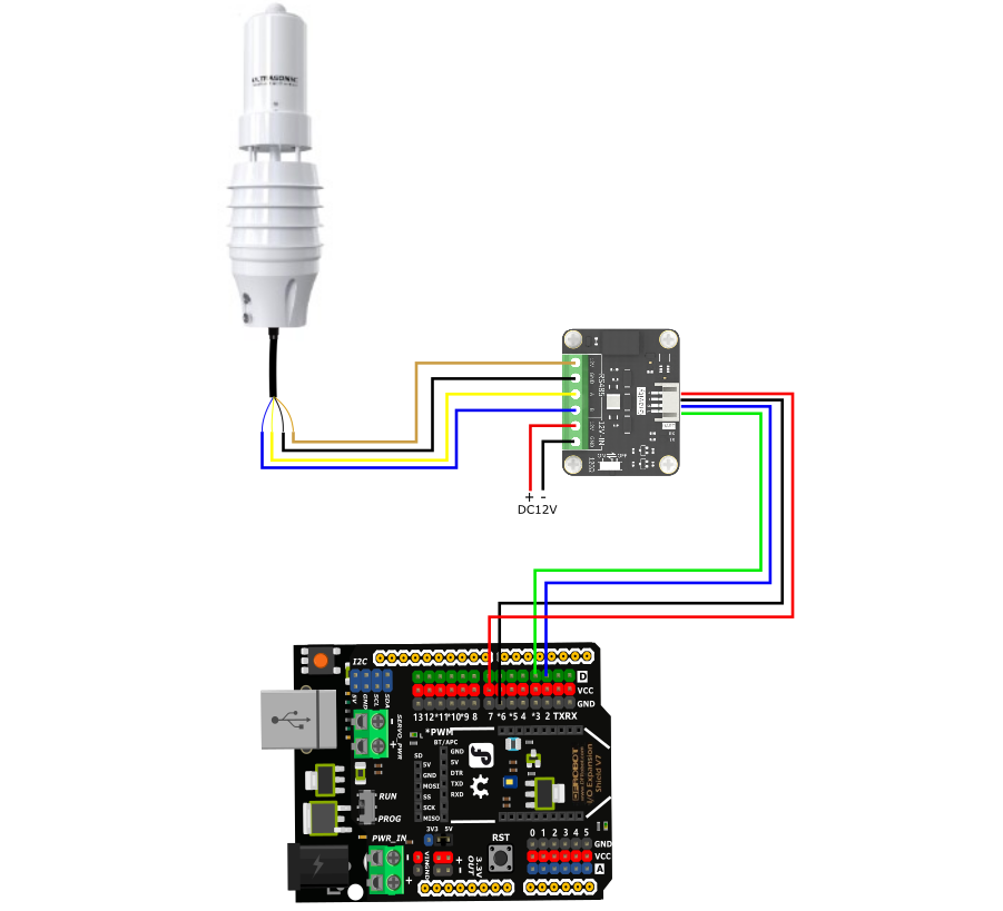
| Brown line | VCC | Power input positive pole, DC10-30V power supply |
| Black line | GND | Power ground wire |
| Yellow line | 485-A | RS485 data line A |
| Blue line | 485-B | RS485 data line B |
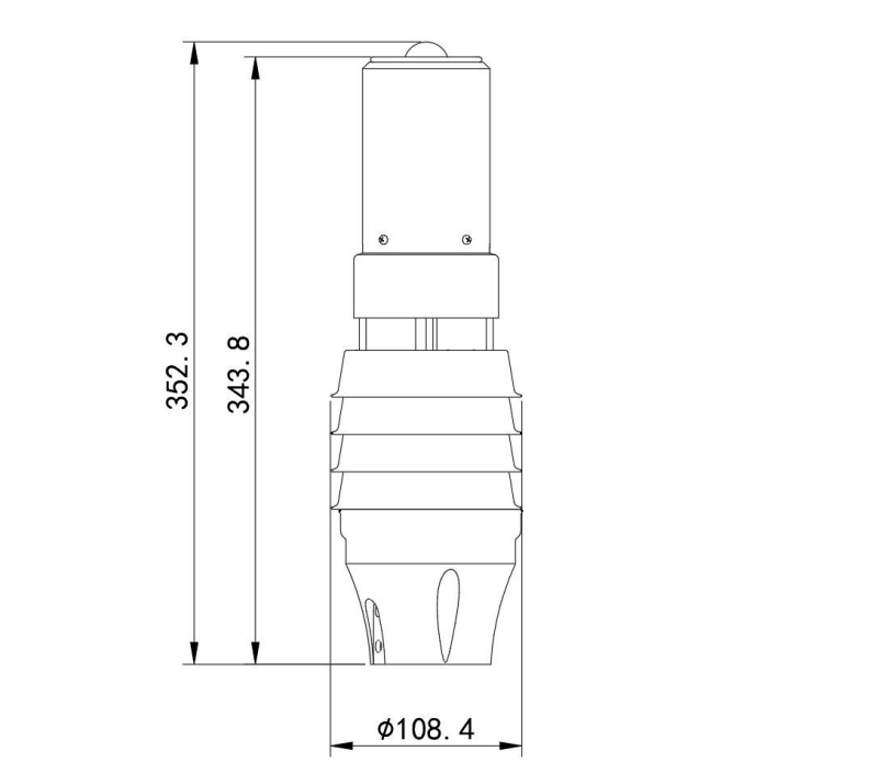
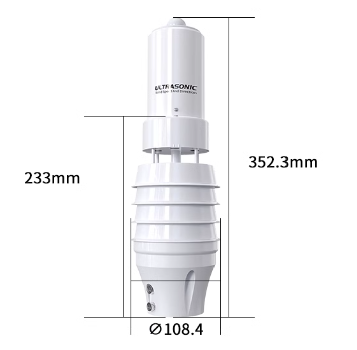
Dimensional Drawing


Communication Protocol
1. Basic communication parameters
| Interface | Encoding | Data bits | Parity bits | Stop bits | Error checking | Baud rate |
|---|---|---|---|---|---|---|
| RS485 | 8-bit binary | 8 | None | 1 | CRC | 1200bit/s, 2400bit/s, 4800bit/s, 9600bit/s, 19200bit/s, 38400bit/s, 57600bit/s, 115200bit/s configurable, default 4800bit/s |
2. Data frame format definition
Using Modbus-RTU communication protocol, the format is as follows:
Initial structure ≥4 bytes of time
Address code = 1 byte
Function code = 1 byte
Data area = N bytes
Error check = 16-bit CRC code
End structure ≥4 bytes of time
Address code: The address of the sensor, which is unique in the communication network (factory default 0x01).
Function code: The function indication of the command sent by the host. This sensor reads the register function code 0x03 and writes the register function code 0x06
Data area: The data area is the specific communication data. Note that the high byte of 16-bit data is in front!
CRC code: A two-byte check code.
Host inquiry frame structure:
| Address code | Function code | Register start address | Register length | Check code low bit | Check code high bit |
|---|---|---|---|---|---|
| 1byte | 1byte | 2byte | 2byte | 1byte | 1byte |
Slave response frame structure:
| Address code | Function code | Number of valid bytes | Data area 1 | Data area 2 | Nth data area | Check code |
|---|---|---|---|---|---|---|
| 1byte | 1byte | 1byte | 2byte | 2byte | 2byte | 2byte |
General register address
| Register address | PLC or configuration address | Content | Supported function code | Definition description |
|---|---|---|---|---|
| 01F4H | 40501 | Wind speed value | 0x03 | 100 times the actual value |
| 01F6H | 40503 | Wind direction (0-7 gears) | 0x03 | Actual value (0 for due north, increasing value clockwise, 2 for due east) |
| 01F7H | 40504 | Wind direction (0-360°) | 0x03 | Actual value (0° for due north, increasing value clockwise, 90° for due east) |
| 01F8H | 40505 | Humidity value | 0x03 | 10 times the actual value |
| 01F9H | 40506 | Temperature value | 0x03 | 10 times of actual value |
| 01FAH | 40507 | Noise value | 0x03 | 10 times of actual value |
| 01FBH | 40508 | PM2.5 value | 0x03 | Actual value |
| 01FCH | 40509 | PM10 value | 0x03 | Actual value |
| 01FDH | 40510 | Atmospheric pressure value | 0x03 | Actual value |
| 01FEH | 40511 | High 16 bits of illumination value | 0x03 | Actual value |
| 01FFH | 40512 | Low 16 bits of illumination value | 0x03 | Actual value |
| 0200H | 40513 | Illumination value | 0x03 | Actual value |
| 0201H | 40514 | Rainfall value | 0x03 | 10 times the actual value |
| 07D0H | 42001 | Device address | 0x03/0x06 | 1~254 (factory default 1) |
| 07D1H | 42002 | Device baud rate | 0x03/0x06 | 0 represents 2400, 1 represents 4800, 2 represents 9600, 3 represents 19200, 4 represents 38400, 5 represents 57600, 6 represents 115200, 7 represents 1200 |
Calibration register address
| Register address | Content | Supported function code | Definition description |
|---|---|---|---|
| 6000H | Wind direction offset register | 0x06 | 0 represents the normal direction, 1 represents the direction offset by 180 degrees |
| 6001H | Wind speed zeroing register | 0x06 | Write 0xAA, wait for 10 seconds, and the device will be zeroed |
| 6002H | Rainfall zeroing register | 0x06 | Write 0x5A, and the rainfall value will be zeroed |
3. Communication protocol example and explanation
3.1. Read the wind speed value of a single register
Inquiry frame: Read value function code 0x03
| Address code | Function code | Register start address | Register length | Check code low bit | Check code high bit |
|---|---|---|---|---|---|
| 0x01 | 0x03 | 0x00 0xF4 | 0x00 0x01 | 0xC4 | 0x04 |
Response frame:
| Address code | Function code | Return valid bytes | Wind speed value | Check code low bit | Check code high bit |
|---|---|---|---|---|---|
| 0x01 | 0x03 | 0x02 | 0x00 0x7D | 0x78 | 0x65 |
Wind speed value:
007D (hexadecimal) = 125=> Wind speed value = 1.25m/s
3.2, read multiple register humidity and temperature values
Inquiry frame: read numerical function code 0x03
| Address code | Function code | Register start address | Register length | Check code low position | Check code high position |
|---|---|---|---|---|---|
| 0x01 | 0x03 | 0x01 0xF8 | 0x00 0x02 | 0x44 | 0x06 |
Response frame:
| Address code | Function code | Return valid bytes | Humidity value | Temperature value | Check code low position | Checksum high position |
|---|---|---|---|---|---|---|
| 0x01 | 0x03 | 0x04 | 0x02 0x92 | 0xFF 0x9B | 0x5A | 0x3D |
Humidity value:
0292 (hexadecimal) = 658=> Humidity value = 65.8%RH
Temperature value: When the temperature is lower than 0℃, upload in the form of complement
FF9B (hexadecimal) = -101=> Temperature value = -10.1°C
3.3, modify the current address
Inquiry frame: (modify the current address to 0x02)
| Address code | Function code | Register address | Modify value | Checksum low position | Checksum high position |
|---|---|---|---|---|---|
| 0x01 | 0x06 | 0x07 0xD0 | 0x00 0x02 | 0x08 | 0x86 |
Response frame:
| Address code | Function code | Register address | Modify value | Check code low bit | Check code high bit |
|---|---|---|---|---|---|
| 0x01 | 0x06 | 0x07 0xD0 | 0x00 0x02 | 0x08 | 0x86 |
3.4, Modify the current baud rate
Inquiry frame: (Modify the current baud rate to 9600)
| Address code | Function code | Register address | Modify value | Check code low bit | **Check code high ** |
|---|---|---|---|---|---|
| 0x01 | 0x06 | 0x07 0xD1 | 0x00 0x02 | 0x59 | 0x46 |
Response frame:
| Address code | Function code | Register address | Modify value | **Check code low ** | **Check code high ** |
|---|---|---|---|---|---|
| 0x01 | 0x06 | 0x07 0xD1 | 0x00 0x02 | 0x59 | 0x46 |
3.5. Query current address and baud rate
Inquiry frame:
| Address code | Function code | Register address | Data length | Check code low bit | Check code high bit |
|---|---|---|---|---|---|
| 0xFF | 0x03 | 0x07 0xD0 | 0x00 0x02 | 0xD1 | 0x58 |
Response frame:
| Address code | Function code | Return valid bytes | Address | Baud rate | Check code low bit | Check code high bit |
|---|---|---|---|---|---|---|
| 0x01 | 0x03 | 0x04 | 0x00 0x01 | 0x00 0x01 | 0x6A | 0x33 |
The real address of the device is 01, and the baud rate is 0x01, that is, 4800.
Tutorial
Requirements
-
Hardware
- DFRduino UNO R3 (or similar) x 1
- Gravity: Active Isolated RS485 to UART Signal Adapter Module x1
- RS485 7-in-1 Weather Station Sensor x1
-
Software
Connection Diagram
If the power of the RS485 device is small and the required current is less than 12V-160mA, the RS485 to UART signal conversion module does not require a 12V external power supply, making wiring more convenient.

Sample Code
#include <SoftwareSerial.h>
SoftwareSerial mySerial(2, 3);                                         //TX,RX
uint8_t Com[8] = { 0x01, 0x03, 0x01, 0xF4, 0x00, 0x04, 0x04, 0x07 }; //Wind speed and direction
uint8_t Com1[8] = { 0x01, 0x03, 0x01, 0xF8, 0x00, 0x02, 0x44, 0x06 }; //Temperature and humidity
uint8_t Com2[8] = { 0x01, 0x03, 0x01, 0xFD, 0x00, 0x03, 0x95, 0xC7 }; //Atmospheric pressure, light
uint8_t Com3[8] = { 0x01, 0x03, 0x02, 0x01, 0x00, 0x01, 0xD4, 0x72 }; //Rainfall
float tem, hum, ws, ap;
int wd, wdangle, lux;

void setup() {
  Serial.begin(9600);
  mySerial.begin(4800);
}
void loop() {
  readhumiture();
  Serial.print("TEM = ");
  Serial.print(tem, 1);
  Serial.print("°C  ");
  Serial.print("HUM = ");
  Serial.print(hum, 1);
  Serial.print("%RH  ");

  readAtmosphericPressure_Light();
  Serial.print("AP = ");
  Serial.print(ap, 1);
  Serial.print("Kpa  ");
  Serial.print("Lux = ");
  Serial.print(lux);
  Serial.print("(lux)  ");

  float Rain = readRainfall();
  Serial.print("Rain = ");
  Serial.print(Rain, 1);
  Serial.println("mm  ");

  readWindSpeed_WindDirection();
  Serial.print("Wind Speed = ");
  Serial.print(ws, 1);
  Serial.print("m/s  ");
  Serial.print("Wind Direction = ");
  Serial.print(wd);
  Serial.print(" WindDirection_Angle = ");
  Serial.print(wdangle);
  Serial.println("° ");
  Serial.println(" ");
  delay(2000);
}

void readWindSpeed_WindDirection(void) {
  uint8_t Data[12] = { 0 };
  uint8_t ch = 0;
  bool flag = 1;
  long timeStart = millis();
  long timeStart1 = 0;
  while (flag) {

    if ((millis() - timeStart1) > 100) {
      while (mySerial.available() > 0) {
        mySerial.read();
      }
      mySerial.write(Com, 8);
      timeStart1 = millis();
    }

    if ((millis() - timeStart) > 1000) {
      Serial.println("Time out");
      return -1;
    }

    if (readN(&ch, 1) == 1) {
      if (ch == 0x01) {
        Data[0] = ch;
        if (readN(&ch, 1) == 1) {
          if (ch == 0x03) {
            Data[1] = ch;
            if (readN(&ch, 1) == 1) {
              if (ch == 0x08) {
                Data[2] = ch;
                if (readN(&Data[3], 10) == 10) {
                  if (CRC16_2(Data, 11) == (Data[11] * 256 + Data[12])) {
                    ws = (Data[3] * 256 + Data[4]) / 100.00;
                    wd = Data[7] * 256 + Data[8];
                    wdangle = Data[9] * 256 + Data[10];
                    flag = 0;
                  }
                }
              }
            }
          }
        }
      }
    }
  }
}


void readhumiture(void) {
  uint8_t Data[10] = { 0 };
  uint8_t ch = 0;
  bool flag = 1;
  long timeStart = millis();
  long timeStart1 = 0;
  while (flag) {

    if ((millis() - timeStart1) > 100) {
      while (mySerial.available() > 0) {
        mySerial.read();
      }
      mySerial.write(Com1, 8);
      timeStart1 = millis();
    }

    if ((millis() - timeStart) > 1000) {
      Serial.println("Time out1");
      return -1;
    }

    if (readN(&ch, 1) == 1) {
      if (ch == 0x01) {
        Data[0] = ch;
        if (readN(&ch, 1) == 1) {
          if (ch == 0x03) {
            Data[1] = ch;
            if (readN(&ch, 1) == 1) {
              if (ch == 0x04) {
                Data[2] = ch;
                if (readN(&Data[3], 6) == 6) {
                  if (CRC16_2(Data, 7) == (Data[7] * 256 + Data[8])) {
                    hum = (Data[3] * 256 + Data[4]) / 10.00;
                    tem = (Data[5] * 256 + Data[6]) / 10.00;
                    flag = 0;
                  }
                }
              }
            }
          }
        }
      }
    }
  }
}


void readAtmosphericPressure_Light(void) {
  uint8_t Data[10] = { 0 };
  uint8_t ch = 0;
  long timeStart = millis();
  long timeStart1 = 0;
  bool flag = 1;
  while (flag) {

    if ((millis() - timeStart1) > 100) {
      while (mySerial.available() > 0) {
        mySerial.read();
      }
      mySerial.write(Com2, 8);
      timeStart1 = millis();
    }


    if ((millis() - timeStart) > 1000) {
      Serial.println("Time out2");
      return -1;
    }

    if (readN(&ch, 1) == 1) {
      if (ch == 0x01) {
        Data[0] = ch;
        if (readN(&ch, 1) == 1) {
          if (ch == 0x03) {
            Data[1] = ch;
            if (readN(&ch, 1) == 1) {
              if (ch == 0x06) {
                Data[2] = ch;
                if (readN(&Data[3], 8) == 8) {
                  if (CRC16_2(Data, 9) == (Data[9] * 256 + Data[10])) {
                    ap = (Data[3] * 256 + Data[4]) / 10.00;
                    lux = Data[5] << 24 | Data[6] << 16 | Data[7] << 8 | Data[8];
                    flag = 0;
                  }
                }
              }
            }
          }
        }
      }
    }
  }
}

float readRainfall(void) {
  uint8_t Data[10] = { 0 };
  uint8_t ch = 0;
  long timeStart = millis();
  long timeStart1 = 0;
  bool flag = 1;
  float data;
  while (flag) {

    if ((millis() - timeStart1) > 100) {
      while (mySerial.available() > 0) {
        mySerial.read();
      }
      mySerial.write(Com3, 8);
      timeStart1 = millis();
    }


    if ((millis() - timeStart) > 1000) {
      Serial.println("Time out3");
      return -1;
    }

    if (readN(&ch, 1) == 1) {
      if (ch == 0x01) {
        Data[0] = ch;
        if (readN(&ch, 1) == 1) {
          if (ch == 0x03) {
            Data[1] = ch;
            if (readN(&ch, 1) == 1) {
              if (ch == 0x02) {
                Data[2] = ch;
                if (readN(&Data[3], 4) == 4) {
                  if (CRC16_2(Data, 5) == (Data[5] * 256 + Data[6])) {
                    data = (Data[3] * 256 + Data[4]) / 10.00;
                    flag = 0;
                  }
                }
              }
            }
          }
        }
      }
    }
  }
  return data;
}


uint8_t readN(uint8_t *buf, size_t len) {
  size_t offset = 0, left = len;
  int16_t Tineout = 500;
  uint8_t *buffer = buf;
  long curr = millis();
  while (left) {
    if (mySerial.available()) {
      buffer[offset] = mySerial.read();
      offset++;
      left--;
    }
    if (millis() - curr > Tineout) {
      break;
    }
  }
  return offset;
}

unsigned int CRC16_2(unsigned char *buf, int len) {
  unsigned int crc = 0xFFFF;
  for (int pos = 0; pos < len; pos++) {
    crc ^= (unsigned int)buf[pos];
    for (int i = 8; i != 0; i--) {
      if ((crc & 0x0001) != 0) {
        crc >>= 1;
        crc ^= 0xA001;
      } else {
        crc >>= 1;
      }
    }
  }

  crc = ((crc & 0x00ff) << 8) | ((crc & 0xff00) >> 8);
  return crc;
}
Expected Results
Print the collected ultrasonic wind speed and direction values, temperature values, humidity values, atmospheric pressure values, light values, and rainfall values
Installation Instructions
When measuring wind speed and direction, the N-shaped direction on the weather station sensor should be installed facing due north to avoid errors.
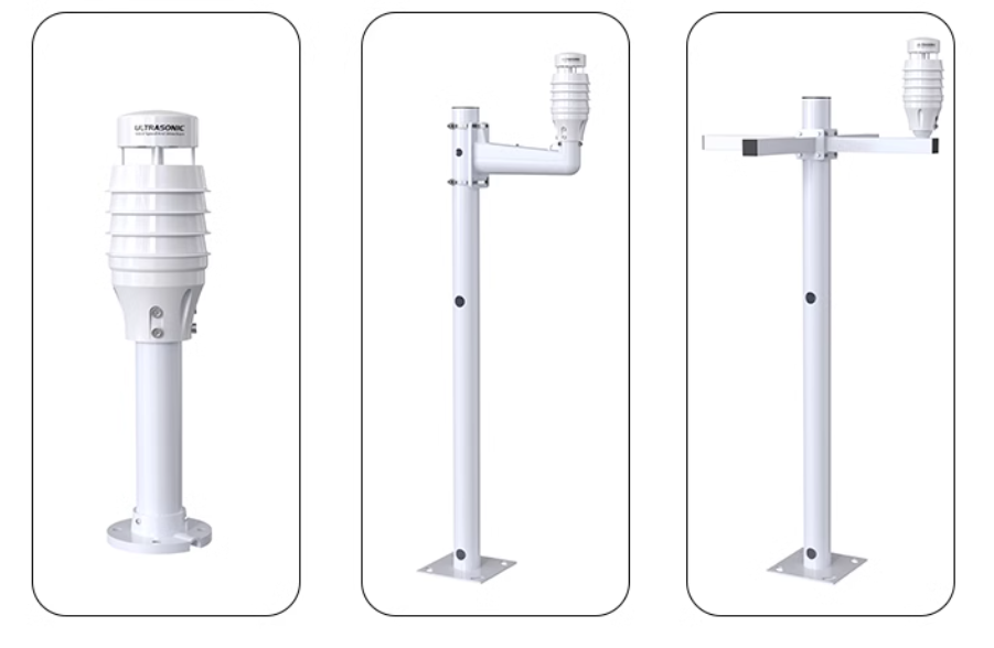
The applicable range of the bottom mounting bar: 46-51mm

The following installation methods are recommended (the bracket needs to be purchased or built by yourself)

FAQ
- The computer has multiple COM ports, and the selected port is incorrect.
- The device address is wrong, or there are devices with duplicate addresses (all factory defaults are 1).
- Baud rate, check mode, data bit, stop bit error.
- Host polling interval and waiting response time are too short, both need to be set above 200ms.
- 485 bus is disconnected, or A and B lines are connected in reverse.
- Too many devices or too long wiring, power supply should be provided nearby, 485 enhancer should be added, and 120Ω terminal resistance should be added.
- USB to 485 driver is not installed or damaged.
- Equipment is damaged.
Note: To ensure the accuracy of the equipment, please clean the lower surface of the measuring area of the equipment regularly to keep it clean and free of dust or other foreign matter.
For any questions, advice or cool ideas to share, please visit the DFRobot Forum.
