Introduction
This infrared carbon dioxide sensor uses the principle of non-dispersive infrared (NDIR technology) to detect CO2 in the air. The measurement range is 400~5000PPM, supports manual calibration, and the measurement data is more accurate. The response time is 5s. The indicator light flashes once each time the response occurs, and the working status of the sensor can be viewed intuitively.
The infrared carbon dioxide sensor uses RS485 output interface and standard Modbus-RTU communication protocol. It can be used with Gravity: RS485 to UART active isolation signal conversion module (DFR0845) to read CO2 value on Arduino UNO R3, quickly build a test environment, simple wiring method, and easy to use.
The infrared carbon dioxide sensor has IP65 protection effect, and the probe is equipped with a waterproof and breathable membrane. The polymer waterproof material has good air permeability, which can effectively prevent water vapor and dust from entering. It can be used for indoor CO2 concentration monitoring, pipeline CO2 concentration monitoring, greenhouse plant environment monitoring, and fresh air system environment detection.
Features
- NDIR technology, measuring range 400~5000PPM
- Threaded fixed installation design, easy installation
- Protection grade IP65, longer service life
- RS485 interface, standard Modbus-RTU protocol
Applications
- Indoor CO2 concentration monitoring
- Pipeline CO2 concentration monitoring
- Greenhouse plant environment monitoring
- Fresh air system environment testing
Specifications:
- Power supply voltage: DC12V
- Working current: <10mA
- Output mode: RS485
- Measurement range: 400-5000ppm
- Accuracy: 400-2000ppm@±50ppm, >2000ppm@±100ppm
- Response time: 5s
- Stabilization time: 60s
- Working temperature: -30~80°C
- Working humidity: 5~90%RH
- Storage temperature: -30~80°C
- Storage humidity: 5~90%RH
- Casing material: plastic
- Protection level: IP65
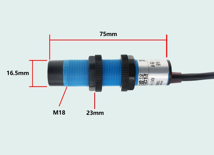
- Mounting thread diameter: M18
- Size: 75*16.5mm
- Sensor cable length: 1m
Board Overview
| Num | Label | Description |
|---|---|---|
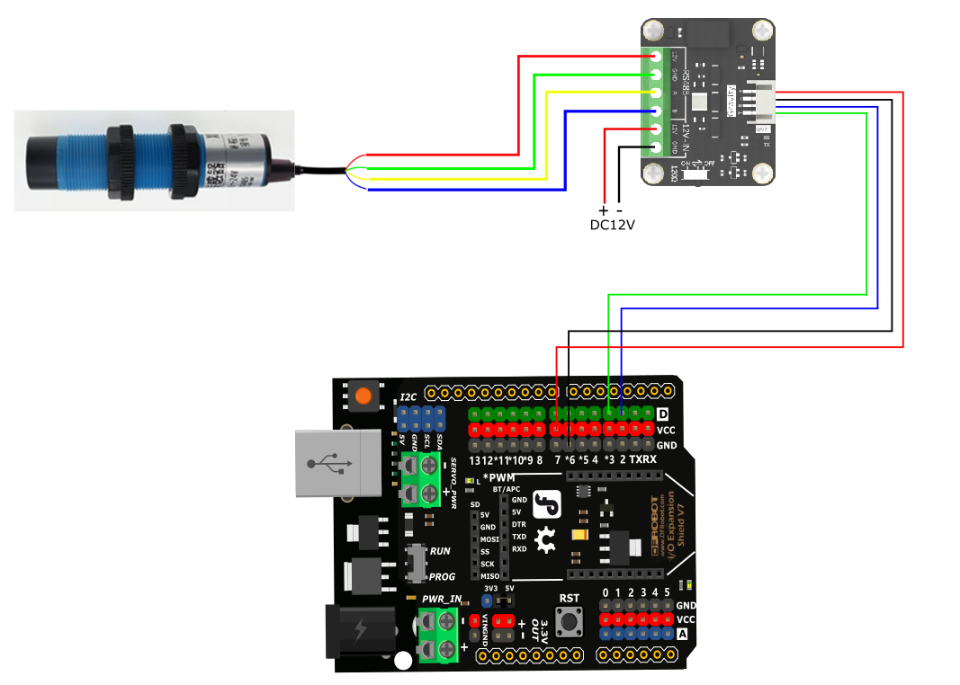
| Red line | VCC | Power input positive pole, DC12V power supply |
| Green line | GND | Power ground wire |
| Yellow line | 485-A | RS485 data line A |
| Blue line | 485-B | RS485 data line B |
Dimensional Drawing

Communication Protocol
1. Basic communication parameters
| Interface | Encoding | Data bit | Parity bit | Stop bit | Error check | Baud rate |
|---|---|---|---|---|---|---|
| RS485 | 8-bit binary | 8 | None | 1 | CRC | 2400bit/s, 4800bit/s, 9600 bit/s,19200bit/s,38400bit/s, 115200bit/s can be set, default is 9600bit/s |
2. Data frame format definition
Using Modbus-RTU communication protocol, the format is as follows:
Initial structure ≥4 bytes of time
Address code = 1 byte
Function code = 1 byte
Data area = N bytes
Error check = 16-bit CRC code
End structure ≥4 bytes of time
Address code: The address of the sensor, which is unique in the communication network (factory default 0x01).
Function code: The function indication of the command sent by the host. This sensor reads the register function code 0x03 and writes the register function code 0x06
Data area: The data area is the specific communication data. Note that the high byte of 16-bit data is in front!
CRC code: A two-byte check code.
Host inquiry frame structure:
| Address code | Function code | Register start address | Register length | Check code low bit | Check code high bit |
|---|---|---|---|---|---|
| 1byte | 1byte | 2byte | 2byte | 1byte | 1byte |
Slave response frame structure:
| Address code | Function code | Number of valid bytes | Data area 1 | Data area 2 | Nth data area | Check code |
|---|---|---|---|---|---|---|
| 1byte | 1byte | 1byte | 2byte | 2byte | 2byte | 2byte |
Register address
| Register address | PLC or configuration address | Content | Supported function code | Definition description |
|---|---|---|---|---|
| 0000H | 40001 | CO2 value | 0x03 | Actual value |
| 006BH | CO2 correction value | 0x03/0x06 | The modifiable range is ±1000, that is, the value range is 0-1000 or 64535-65535 | |
| 0066H | 40103 | Device address | 0x03/0x06 | 1~249 (factory default 1) |
| 0067H | 40104 | Device baud rate | 0x03/0x06 | 1 represents 2400, 2 represents 4800, 3 represents 9600, 4 represents 19200, 5 represents 38400, 6 represents 115200 |
3. Communication protocol example and explanation
3.1. Read carbon dioxide value
Inquiry frame: Read value function code 0x03
| Address code | Function code | Register start address | Register length | Check code low bit | Check code high bit |
|---|---|---|---|---|---|
| 0x01 | 0x03 | 0x00 0x00 | 0x00 0x01 | 0x84 | 0x0A |
Response frame:
| Address code | Function code | Return valid bytes | Carbon dioxide value | Check code low bit | Check code high bit |
|---|---|---|---|---|---|
| 0x01 | 0x03 | 0x02 | 0x02 0xFC | 0xB9 | 0x65 |
CO2 value:
02FC (hexadecimal) = 764=> CO2 value = 764ppm
3.2, Read the current CO2 correction value (factory default is 0)
Inquiry frame:
| Address code | Function code | Register start address | Register length | Check code low position | Check code high position |
|---|---|---|---|---|---|
| 0x01 | 0x03 | 0x00 0x6B | 0x00 0x01 | 0xF5 | 0xD6 |
Response frame:
| Address code | Function code | Return valid bytes | Correction value | Check code low position | Check code high position |
|---|---|---|---|---|---|
| 0x01 | 0x03 | 0x02 | 0x00 0x64 | 0xB9 | 0xAF |
Calibration value:
0064 (hexadecimal) = 100=> Calibration value = 100ppm
3.3. Modify the CO2 calibration value
When the data is different from the reference standard, we can reduce the display error by adjusting the "calibration value". The calibration difference can be modified in the range of ±1000, that is, the value range is 0-1000 or 64535-65535. For example, when the displayed value is 100 less, we can correct it by adding 100. In the command, 100 is hexadecimal 0x64; if you need to reduce it, you can set a negative value, such as -100, which is calculated as FFFF-64+1=FF9C, which is hexadecimal 0xFF 9C
Inquiry frame:
| Address code | Function code | Register start address | Modify value | Check code low position | Check code high position |
|---|---|---|---|---|---|
| 0x01 | 0x06 | 0x00 0x6B | 0x00 0x64 | 0xF9 | 0xFD |
Response frame:
| Address code | Function code | Register address | Correction value | Check code low position | Check code high position |
|---|---|---|---|---|---|
| 0x01 | 0x06 | 0x00 0x6B | 0x00 0x64 | 0xF9 | 0xFD |
Correction value:
0064 (hexadecimal) = 100=> correction value = 100ppm
3.4, Modify the current address
Inquiry frame: (modify the current address to 0x02)
| Address code | Function code | Register address | Modify value | Check code low bit | Check code high bit |
|---|---|---|---|---|---|
| 0x01 | 0x06 | 0x00 0x66 | 0x00 0x02 | 0xE8 | 0x14 |
Response frame:
| Address code | Function code | Register address | Modify value | Check code low bit | Check code high bit |
|---|---|---|---|---|---|
| 0x02 | 0x06 | 0x00 0x66 | 0x00 0x02 | 0xE8 | 0x27 |
3.5, Modify current baud rate
Inquiry frame: (Modify current baud rate to 38400)
| Address code | Function code | Register address | Modify value | Check code low bit | Check code high bit |
|---|---|---|---|---|---|
| 0x01 | 0x06 | 0x00 0x67 | 0x00 0x05 | 0xF8 | 0x16 |
Response frame:
| Address code | Function code | Register address | Modify value | Check code low bit | Check code high bit |
|---|---|---|---|---|---|
| 0x01 | 0x06 | 0x00 0x67 | 0x00 0x05 | 0xF8 | 0x16 |
3.6, Query current address, baud rate
Inquiry frame:
| Address code | Function code | Register address | Data length | Check code low bit | Check code high bit |
|---|---|---|---|---|---|
| 0xFA | 0x03 | 0x00 0x66 | 0x00 0x02 | 0x31 | 0x9F |
Response frame:
| Address code | Function code | Return valid bytes | Address | Baud rate | Check code low bit | Check code high bit |
|---|---|---|---|---|---|---|
| 0x01 | 0x03 | 0x04 | 0x00 0x01 | 0x00 0x03 | 0xEB | 0xF2 |
The real address of the device read is 01, and the baud rate is 0x03, which is 9600.
Tutorial
Requirements
-
Hardware
- DFRduino UNO R3 (or similar) x 1
- Gravity: Active Isolated RS485 to UART Signal Adapter Module x1
- RS485 Infrared CO2 Sensor(400-5000ppm) x1
-
Software
Connection Diagram
If the power of the RS485 device is small and the required current is less than 12V-160mA, the RS485 to UART signal conversion module does not require a 12V external power supply, making wiring more convenient.

Sample Code
Note: The CO2 concentration value output during the preheating time will gradually stabilize. Please ignore the CO2 concentration value within 5 minutes of preheating.
#include <SoftwareSerial.h>
SoftwareSerial mySerial(2,3);
uint8_t Com[8] = { 0x01, 0x03, 0x00, 0x00, 0x00, 0x01, 0x84, 0x0A };
int CO2;
void setup() {
  Serial.begin(9600);
  mySerial.begin(9600);
}
void loop() {
  readCO2();
  Serial.print("CO2 = ");
  Serial.print(CO2);
  Serial.println(" ppm");
  delay(4000);
}
void readCO2(void) {
  uint8_t Data[10] = { 0 };
  uint8_t ch = 0;
  bool flag = 1;
  while (flag) {
    delay(100);
    mySerial.write(Com, 8);
    delay(10);
    if (readN(&ch, 1) == 1) {
      if (ch == 0x01) {
        Data[0] = ch;
        if (readN(&ch, 1) == 1) {
          if (ch == 0x03) {
            Data[1] = ch;
            if (readN(&ch, 1) == 1) {
              if (ch == 0x02) {
                Data[2] = ch;
                if (readN(&Data[3], 4) == 4) {
                 if (CRC16_2(Data, 5) == (Data[5] * 256 + Data[6])) {
                    CO2 = Data[3] * 256 + Data[4];
                    flag = 0;
                  }
                }
              }
            }
          }
        }
      }
    }
     mySerial.flush();
  }
}

uint8_t readN(uint8_t *buf, size_t len) {
  size_t offset = 0, left = len;
  int16_t Tineout = 500;
  uint8_t *buffer = buf;
  long curr = millis();
  while (left) {
    if (mySerial.available()) {
      buffer[offset] = mySerial.read();
      offset++;
      left--;
    }
    if (millis() - curr > Tineout) {
      break;
    }
  }
  return offset;
}

unsigned int CRC16_2(unsigned char *buf, int len) {
  unsigned int crc = 0xFFFF;
  for (int pos = 0; pos < len; pos++) {
    crc ^= (unsigned int)buf[pos];
    for (int i = 8; i != 0; i--) {
      if ((crc & 0x0001) != 0) {
        crc >>= 1;
        crc ^= 0xA001;
      } else {
        crc >>= 1;
      }
    }
  }

  crc = ((crc & 0x00ff) << 8) | ((crc & 0xff00) >> 8);
  return crc;
}
Expected Results
Print the collected CO2 value.
FAQ
- The computer has multiple COM ports, and the selected port is incorrect.
- The device address is wrong, or there are devices with duplicate addresses (all factory defaults are 1).
- Baud rate, check mode, data bit, stop bit error.
- Host polling interval and waiting response time are too short, both need to be set above 200ms.
- 485 bus is disconnected, or A and B lines are connected in reverse.
- Too many devices or too long wiring, power supply should be provided nearby, 485 enhancer should be added, and 120Ω terminal resistance should be added.
- USB to 485 driver is not installed or damaged.
- Equipment is damaged.
Note: To ensure the accuracy of the equipment, please clean the lower surface of the measuring area of the equipment regularly to keep it clean and free of dust or other foreign matter.
For any questions, advice or cool ideas to share, please visit the DFRobot Forum.
