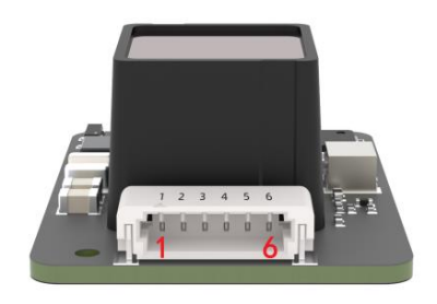
Introduction
The TFS20-L is a fully integrated single-channel dToF ranging compact module, incorporating a high-sensitivity infrared-enhanced SPAD sensor, with a measurement range of up to 20 meters. Utilizing an all-in-one SPAD chip solution, histogram statistics algorithms, and a fast TDC architecture, it achieves high-precision ranging while offering 15m@100 Klux sunlight resistance and reflectivity correction functionality.
Compact Size, High Performance
With its small dimensions, lightweight design, and exceptional accuracy and range, the TFS20-L delivers outstanding performance even under strong ambient light, making it an ideal choice for miniaturized dToF applications.
Rich Features, Broad Applications
The TFS20-L integrates a power module, operates on a 3.3V single power supply, and features built-in temperature compensation. It supports I2C and UART interfaces for easy integration and use, along with a compact and reliable optical package. Suitable for UAV altitude hold, UAV-assisted landing, robot anti-drop, and smart device triggering.
Features
- Compact size, lightweight, and easy integration
- Strong ambient light resistance for stable indoor/outdoor measurements
- Dual output interfaces: UART and I2C
Applications
- UAV altitude hold
- UAV-assisted landing
- Robot anti-drop
- Smart device triggering
Specifications
- Performance Parameter
- Measurement range:
0.2–20m@90%reflectivity,0Klux;0.2–12m@10%reflectivity,0Klux;
0.2–15m@90%reflectivity,100Klux; 0.2–9m@10%reflectivity,100Klux - Accuracy: ±6cm @0.2–6m; 1%@≥6m
- Precision: 2cm (0.2–6m)
- Distance resolution: 1cm
- Frame rate: 0/20/50/100 (default)/250Hz
- Ambient light resistance: 100 Klux
- Optical Performance
- Light source: VCSEL
- Central wavelength: 905nm
- Field of view (FoV): <2°
- Laser safety class: Class 1 Eye-safe [EN60825]
- Mechanical & Electrical Parameters
- Average power consumption: ≤0.43W
- Peak current: <130mA @ 3.3V
- Supply voltage: DC 3.3±9%V
- Communication level: LVTTL (3.3V)
- Operating temperature: -20℃ to +60℃
- Storage temperature: -40℃ to +85℃
- Dimensions: 21×15×7.87mm
- Weight: 1.35g
- Hardware interface: 0.8mm 6-pin (Model: WF08006-01207)
Board Overview

Num | Label | Description |
---|---|---|
PIN1 | Red line | 3.3V laser power supply |
PIN2 | Black line | 3.3V power supply positive |
PIN3 | Yellow line | TXD(3.3V)/SDA |
PIN4 | Green line | RXD(3.3V)/SCL |
PIN5 | Blue line | GPIO communication chip select |
PIN6 | White line | GND |
TFS20-L switches the output mode through hardware. When PIN5 is grounded, it is UART mode, and when PIN5 is left floating, it is I2C mode.
Dimensional Drawing

Tutorial
Requirements
- Hardware
- DFRduino UNO R3 x 1
- Gravity: IO Expansion Shield for Arduino V7.1 x1
- TFS20-L LiDAR x1
- 0.8mm to 2.54mm Dupont connector cable (20cm) x1


- Software
- Arduino IDE
- Download the DFRobot_TFmini library, which is a general library for TF series single-point LiDAR.
UART Mode Connection Diagram
Connect pin 5 of TFS20-L to GND for UART mode. Adjust the VCC voltage of Arduino UNO R3 development board to 3.3V. Do not power TFS20-L with 5V. It will get hot if powered with 5V for a long time.

Sample Code
#include <DFRobot_TFmini.h>
SoftwareSerial mySerial(8, 9); // RX, TX
DFRobot_TFmini TFmini;
uint16_t distance, strength;
void setup() {
Serial.begin(9600);
TFmini.begin(mySerial);
}
void loop() {
if (TFmini.measure()) {
distance = TFmini.getDistance();
strength = TFmini.getStrength();
Serial.print("Distance = ");
Serial.print(distance);
Serial.println("cm");
Serial.print("Strength = ");
Serial.println(strength);
delay(100);
}
delay(100);
}
Expected Results
Print the collected distance value and signal strength value.

I2C Mode Connection Diagram
TFS20-L 5th pin is left floating in I2C mode, adjust the VCC voltage of Arduino UNO R3 development board to 3.3V, TFS20-L should not be powered by 5V, as it will get hot if powered by 5V for a long time.

Sample Code
#include <Wire.h>
#define deviceaddress 0x10
uint16_t data;
uint8_t COM[4] = { 0 };
uint8_t COM1[1] = { 0 };
uint8_t COM2[1] = { 0x64 }; //Frame rate value, default 100hz
uint8_t COM3[1] = { 0x01}; //Save register
uint8_t COM4[1] = { 0x02}; //Restart register
void i2c_writeN(uint8_t registerAddress, uint8_t *buf, size_t len) {
Wire.beginTransmission(deviceaddress);
Wire.write(registerAddress);
Wire.write(buf, len);
Wire.endTransmission();
}
int16_t i2c_readN(uint8_t registerAddress, uint8_t *buf, size_t len) {
uint8_t i = 0;
Wire.beginTransmission(deviceaddress);
Wire.write(registerAddress);
if (Wire.endTransmission(false) != 0) {
return -1;
}
Wire.requestFrom(deviceaddress, len);
delay(100);
while (Wire.available()) {
buf[i++] = Wire.read();
}
return i;
}
void setup() {
Wire.begin();
Serial.begin(9600);
/*
* Modify and save registers, open when you need to modify the frame rate
*/
// i2c_writeN(0x26, COM2, 1);
// delay(200);
// i2c_writeN(0x20, COM3, 1);
// delay(200);
// i2c_writeN(0x21, COM4, 1);
}
void loop() {
i2c_readN(0x00, COM, 2);
data = COM[1] << 8 | COM[0];
delay(200);
i2c_readN(0x26, COM1, 1);
Serial.print("Distance=");
Serial.print(data);
Serial.print("cm");
Serial.print(" FPS =");
Serial.print(COM1[0]);
Serial.println("hz");
delay(100);
}
Expected Results
Print the collected distance value and frame rate value.

FAQ
- UART and I2C output modes are switched via 5-pin GPIO
- TFS20-L operates at 3.3V, do not power it with 5V, it may get hot easily