Introduction
The AI binocular vision recognition sensor uses an Al main chip and is equipped with two 2-megapixel high-definition cameras. The cameras use color and infrared cameras respectively, which can be recognized normally in dark environments. The module uses the LINUX fast start operating system to achieve fast startup. The local embedded face binocular 3D liveness detection algorithm, the deep neural network recognition algorithm based on big data training, the QR code recognition algorithm, and the palm print and palm vein algorithm realize the face, QR code, and palm vein recognition functions, and output the recognition results through UART. At the same time, the color camera UVC video can be transmitted through USB (expandable to UAC audio and video function) for local audio and video display and playback or remote video and audio transmission functions.
The AI binocular vision recognition sensor starts quickly and supports both power-off low power consumption and constant power supply dual modes. In the constant power supply mode, when the module is set to low-power automatic detection mode, automatic detection and recognition of faces, palm veins and QR codes can be realized, which is convenient for docking with third-party products and realizes multiple identity authentication functions.
It provides UART protocol, supports third-party integrated docking, and realizes audio and video transmission docking of identity recognition functions. The AI binocular vision recognition sensor has no computing power requirements for third-party devices, is plug-and-play, and has strong versatility. It can be used to upgrade various new and old products that require multiple identity authentication methods such as face, QR code, and vein and palm print.
Features
- Binocular 3D liveness detection resists spoofing via photos/videos
- Neural network-based algorithms: face recognition, palm vein recognition, QR code decoding
- Local storage: 1,000 faces + 1,000 palm vein templates
- Operates in complete darkness and non-direct sunlight outdoors
- Zero host-computation requirement; all AI processing occurs offline on-module
Applications
- Smart home systems
- Smart door locks
- Self-service retail payment terminals
- 3D face/palm vein payment systems
- Palm vein authentication systems
Specifications
- Hardware Parameters
- SoC: Arm CPU@900MHz, [email protected], RISC-V@600MHz
- DDR2: 64MB
- Flash: 32MB
- Cameras: Dual 1/5” CMOS, 2MP, dual MIPI interfaces
- Lens: FOV: 83° diagonal; optimal focus: 60cm
- LED: IR@850nm, RGB@650nm (90° illumination)
- USB: UVC video transmission (expandable to UAC); MJPEG output (H.264/YUY2 expandable)
- Communication: UART@115200 baud
- Power Parameters
- Supply voltage: 5-12V
- Operating current: 320-330mA@8V
- Standby current: 120–130mA (auto-detection mode)
- Shutdown current: 0µA (non-auto-detection mode)
- Other Parameters
- Operating temperature: -20°C to +60°C
- Storage temperature: -30°C to +70°C
- Humidity: 10–93% RH (non-condensing)
- Audio I/O: Expandable (speaker/microphone)
- Boot time: 900ms–2.5s (varies with stored user count)
- User capacity: 1,000 faces; 1,000 palm veins
- Algorithms: Binocular liveness detection, deep learning face recognition, palm vein recognition, QR code recognition
- Liveness metrics:
- FAR (False Acceptance Rate) ≤1%
- FRR (False Rejection Rate) ≤1%
- Face recognition:
- Pass rate: 98.85%
- FAR: 0.001%
- Recognition angle: ±20° pitch/yaw; supports multi-angle enrollment
- Detection range:Face: 30–120cm,Palm vein/QR code: 15cm
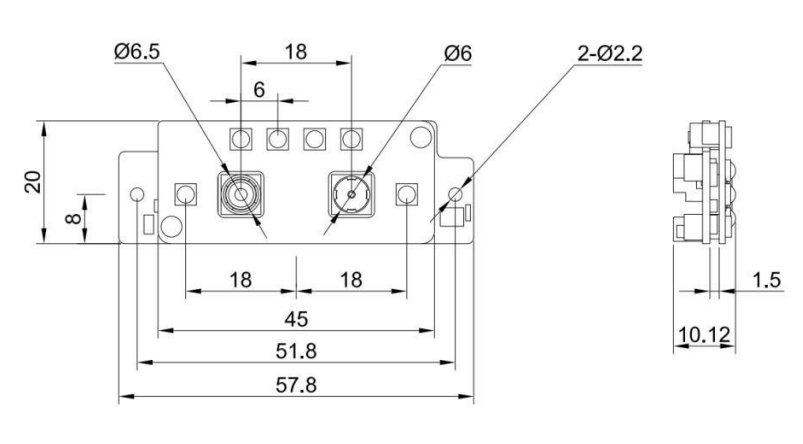
- Dimensions: 57.8×20×10.12mm
Functional diagram

-
Motherboard
The algorithm motherboard uses an AI main chip and a Linux quick-start operating system. It has transplanted face recognition, palm print and vein, and QR code algorithms, and developed application firmware, which mainly realizes the functions of registration and recognition, and outputs recognition results. -
Dual cameras
Includes color and infrared cameras, using a 2-megapixel CMOS chip with an 850 lens and a 650 lens. -
Infrared light & white light
(White light can be used. When white light is not used, black and white images are displayed in the dark) The function of infrared light is to provide real-time fill light for infrared camera. The function of white light is to automatically start fill light when the environment is not bright enough to ensure the clarity of infrared and color images. -
Foam
Used to isolate the fill light and COMS to prevent light from entering COMS and causing image glare. -
Built-in algorithm
- Binocular face liveness detection algorithm
- Deep learning face recognition algorithm
- QR code recognition algorithm
Board Overview

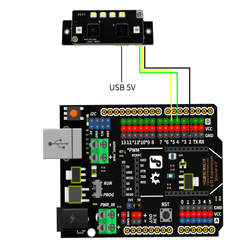
UART interface
| Pin | Color line sequence | Function description |
|---|---|---|
| 1 | Black line | GND |
| 2 | Yellow line | UART_RX |
| 3 | Green line | UART_TX |
| 4 | Red line | VCC 5~12V |
USB interface
Can output video signals for screen display, support standard UVC video, MJPEG/YUY2/H.264 encoding, and have horizontal and vertical screens with multiple resolutions. Can be expanded to realize UAC audio function, can realize voice intercom function.
| Pin | Functional Description |
|---|---|
| 1 | VCC 5V |
| 2 | Floating |
| 3 | DM USB data line D- |
| 4 | DP USB data line D+ |
| 5 | GND |
Microphone interface (reserved)
Mainly used to receive sound signals and realize intercom function
| Pin | Name | Functional Description |
|---|---|---|
| 1 | Negative pole | MIC- |
| 2 | Positive pole | MIC+ |
Speaker interface (reserved)
Mainly used for voice playback
| Pin | Name | Functional Description |
|---|---|---|
| 1 | SPK | 1W/8Ω |
| 2 | SPK | 1W/8Ω |
Dimensional Drawing
Installation height and tilt angle
Depending on the installation height of the product, it is recommended to use an external bracket to adjust the tilt angle of the product to suit user-friendly identification of different heights. The recommended tilt angle and identification height coverage range at various installation heights are shown in the following table:
| Installation height | Recommended tilt angle | Identification distance | Human height coverage range |
|---|---|---|---|
| 130cm | 20° | 30~100cm | 130~200cm |
| 140cm | 12° | 30~100cm | 130~200cm |
| 150cm | 0° | 30~100cm | 130~200cm |

Tutorial
Requirements
- Hardware
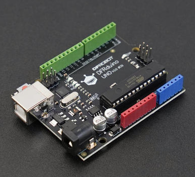
- DFRduino UNO R3 x 1
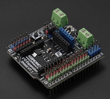
- Gravity: IO Expansion Shield for Arduino V7.1 x1
- AI Binocular Vision Recognition Sensor(Face & Palm Vein & QR Code) x1
- 1.25mm 4-pin to Dupont female connector cable ×1
- USB data cable ×1
- Software
- Arduino IDE
- Download DFRobot_AI10 library
Connection Diagram
The PC USB interface has low power, so it is recommended to use a 5V USB adapter for power supply, which will make the recognition more sensitive.
Registering face & palm print Sample Code
When registering face or palm print, you need to fix the AI visual sensor and pay attention to the recognition distance, 30-120cm for face, 15cm for vein palm print, and 15cm for QR code. Only one face or palm print is registered each time. If you need to register multiple, you can press the reset button of the UNO R3 development board to register other faces or palm prints again.
/*!
 * @file singleRegisteredUser.ino
 * @brief This is an example of using the DFRobot_AI10 library to enroll a single registered user.
 * @copyright	Copyright (c) 2025 DFRobot Co.Ltd (http://www.dfrobot.com)
 * @license The MIT License (MIT)
 * @author [jiali]([email protected])
 * @version V1.0
 * @date 2025-07-14
 * @url https://github.com/DFRobot/DFRobot_AI10
 */
#include "DFRobot_AI10.h"

/* ---------------------------------------------------------------------------------------------------------------------
  *    board   |             MCU                | Leonardo/Mega2560/M0 |    UNO    | ESP8266 | ESP32 |  microbit  |   m0  |
  *     VCC    |            3.3V/5V             |        VCC           |    VCC    |   VCC   |  VCC  |     X      |  vcc  |
  *     GND    |              GND               |        GND           |    GND    |   GND   |  GND  |     X      |  gnd  |
  *     RX     |              TX                |     Serial1 TX1      |     5     |   5/D6  | 25/D2 |     X      |  tx1  |
  *     TX     |              RX                |     Serial1 RX1      |     4     |   4/D7  | 26/D3 |     X      |  rx1  |
  * ----------------------------------------------------------------------------------------------------------------------*/
/* Baud rate cannot be changed , it is 115200 */

  #if defined(ARDUINO_AVR_UNO) || defined(ESP8266)
    SoftwareSerial mySerial(4, 5);
    DFRobot_AI10_UART recognize(&mySerial ,115200);
  #elif defined(ESP32)
    DFRobot_AI10_UART recognize(&Serial1,115200,/*rxD2*/25,/*txD3*/26);
  #else
    DFRobot_AI10_UART recognize(&Serial1 ,115200);
  #endif


void setup() {
  Serial.begin(115200);
  while (!Serial);
  while(!recognize.begin()){
    Serial.println("NO Deivces !");
    delay(1000);
  }
  Serial.println("Device connected!");

  Serial.println("Start to enroll a user...");

  //User enroll result anc info
  sUserData_t udata;

  /*
  *admin permission is required to register a user. eNormal:average person ,eAdmin: administrator
  *userName registered user name, the length is 32 bytes at most
  *timeout is the time to wait for the recognition result, the range is 3-20 seconds
  */

  udata = recognize.enrollUser(/*admin*/eNormal,/*userName*/"User1",/*timeout*/ 5);

  //Check if the registration is successful, if successful, print the user information
  if(udata.result == eSuccess){
    Serial.println("User enrolled successfully!");
    Serial.print("UID: ");
    Serial.println(udata.UID);
    Serial.print("User name: ");
    Serial.println(udata.userName);
    Serial.print("Admin permission: ");
    Serial.println(udata.admin == eNormal ? "Normal":"Admin");
    Serial.print("User enrolled type: ");
    Serial.println(udata.type == eFace ? "Face":"Palm");
  }else if (udata.result == eFailedFaceEnrolled){
    Serial.println("Failed to enroll user, user already enrolled!");
  }else{
    Serial.println("Failed to enroll user!");
  }
}

void loop() {

  delay(100);
}
Expected Results
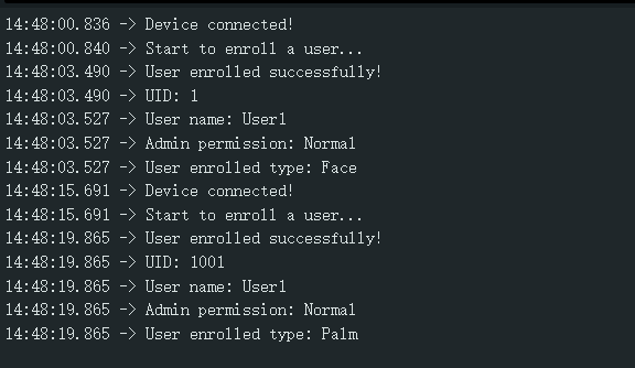
Register through the reset button of the UNO R3 development board. Each reset can register a face or palm print once. Each registration time is 5S. ID 1-1000 is face, and 1001-2000 is vein palm print.
Continuously identify faces, palm prints, and QR codes Sample Code
Continuously identify faces, palm prints, and QR codes, and print the corresponding information through the serial port monitor. If it cannot be recognized, you can adjust the distance or posture slightly and keep it still.
/*!
 * @file continuousRecognition.ino
 * @brief This is an example of using the DFRobot_AI10 library to recognize human faces and QR codes in real-time.
 * @copyright	Copyright (c) 2025 DFRobot Co.Ltd (http://www.dfrobot.com)
 * @license The MIT License (MIT)
 * @author [jiali]([email protected])
 * @version V1.0
 * @date 2025-07-14
 * @url https://github.com/DFRobot/DFRobot_AI10
 */
#include "DFRobot_AI10.h"

/* ---------------------------------------------------------------------------------------------------------------------
  *    board   |             MCU                | Leonardo/Mega2560/M0 |    UNO    | ESP8266 | ESP32 |  microbit  |   m0  |
  *     VCC    |            3.3V/5V             |        VCC           |    VCC    |   VCC   |  VCC  |     X      |  vcc  |
  *     GND    |              GND               |        GND           |    GND    |   GND   |  GND  |     X      |  gnd  |
  *     RX     |              TX                |     Serial1 TX1      |     5     |   5/D6  | 25/D2 |     X      |  tx1  |
  *     TX     |              RX                |     Serial1 RX1      |     4     |   4/D7  | 26/D3 |     X      |  rx1  |
  * ----------------------------------------------------------------------------------------------------------------------*/
/* Baud rate cannot be changed , it is 115200 */

  #if defined(ARDUINO_AVR_UNO) || defined(ESP8266)
    SoftwareSerial mySerial(4, 5);
    DFRobot_AI10_UART recognize(&mySerial ,115200);
  #elif defined(ESP32)
    DFRobot_AI10_UART recognize(&Serial1,115200,/*rxD2*/25,/*txD3*/26);
  #else
    DFRobot_AI10_UART recognize(&Serial1 ,115200);
  #endif

void setup() {
  Serial.begin(115200);
  while (!Serial);
  while(!recognize.begin()){
    Serial.println("NO Deivces !");
    delay(1000);
  }
  Serial.println("Device connected!");

  //Enable face frame
  if(recognize.enableFaceFrame()){
    Serial.println("Face frame enabled!");
  }
}

void loop() {
  //Continuous recognition result

  sRecognitionData_t recDat;

  /* When a human face is detected,  the system automatically starts the recognition process.After the person moves away for
  x seconds, the recognition stops and the module continues with low-power face detection.the range is 3-20s.
   */
  Serial.println("=================================");
  Serial.println("Recognize...");

  recDat = recognize.startContinuousFaceRecognition(/*timeout*/5);

  //Print the recognition result
  if(recDat.result == eSuccess){
    Serial.println("Recognition successful!");
    Serial.print("Recognition type: ");

    if(recDat.type == eQR){
      Serial.println("QR code");
      Serial.print("QR code data: ");
      Serial.println(recDat.QRDdata);
    }else{
      Serial.println(recDat.type == eFace ? "Face" : "Palm");
      Serial.print("User ID: ");
      Serial.println(recDat.userData.UID);
      Serial.print("User Name: ");
      Serial.println(recDat.userData.userName);
      Serial.print("Admin Permission: ");
      Serial.println(recDat.userData.admin == eAdmin ? "Admin" : "Normal");
    }

  }else{
    Serial.println("Recognition failed!");
    Serial.print("Failed code: ");
    Serial.print(recDat.result);

    if(recDat.result == eFailedTimeout){
      Serial.println(" Recognition timed out!");
    }else if(recDat.result == eFailedCamera){
      Serial.println(" Camera error!");
    }else if(recDat.result == eFailedLiveCheck){
      Serial.println(" Live check failed!");
    }else{
      Serial.println();
    }
  }
  Serial.println("=================================");

}
Expected Results
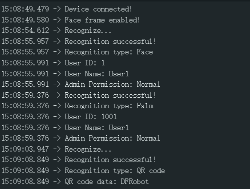
Continuously identify the detected faces, palm prints, and QR codes, and print the corresponding information through the serial port monitor.
User statistics & user deletion Sample Code
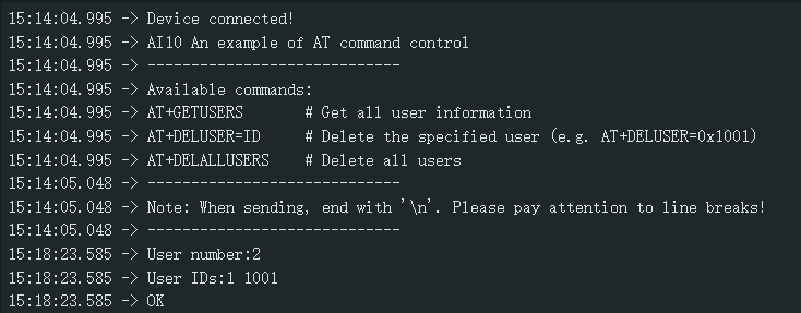
Input command: AT+GETUSERS, query all user numbers and IDs
Input command: AT+DELUSER=1, delete the specified user ID1, 1 can be replaced by other user IDs
Input command: AT+DELALLUSERS, delete all registered users
/*!
 * @file operateUserData.ino
 * @brief This is an example of how to use the DFRobot_AI10 library to operate user data
 * @copyright	Copyright (c) 2025 DFRobot Co.Ltd (http://www.dfrobot.com)
 * @license The MIT License (MIT)
 * @author [jiali]([email protected])
 * @version V1.0
 * @date 2025-07-14
 * @url https://github.com/DFRobot/DFRobot_AI10
 */
#include "DFRobot_AI10.h"

/* ---------------------------------------------------------------------------------------------------------------------
  *    board   |             MCU                | Leonardo/Mega2560/M0 |    UNO    | ESP8266 | ESP32 |  microbit  |   m0  |
  *     VCC    |            3.3V/5V             |        VCC           |    VCC    |   VCC   |  VCC  |     X      |  vcc  |
  *     GND    |              GND               |        GND           |    GND    |   GND   |  GND  |     X      |  gnd  |
  *     RX     |              TX                |     Serial1 TX1      |     5     |   5/D6  | 25/D2 |     X      |  tx1  |
  *     TX     |              RX                |     Serial1 RX1      |     4     |   4/D7  | 26/D3 |     X      |  rx1  |
  * ----------------------------------------------------------------------------------------------------------------------*/
/* Baud rate cannot be changed , it is 115200 */

  #if defined(ARDUINO_AVR_UNO) || defined(ESP8266)
    SoftwareSerial mySerial(4, 5);
    DFRobot_AI10_UART recognize(&mySerial ,115200);
  #elif defined(ESP32)
    DFRobot_AI10_UART recognize(&Serial1,115200,/*rxD2*/25,/*txD3*/26);
  #else
    DFRobot_AI10_UART recognize(&Serial1 ,115200);
  #endif


void setup() {
  Serial.begin(115200);
  while (!Serial);
  while(!recognize.begin()){
    Serial.println("NO Deivces !");
    delay(1000);
  }
  Serial.println("Device connected!");

  Serial.println("AI10 An example of AT command control");
  Serial.println("-----------------------------");
  Serial.println("Available commands:");
  Serial.println("AT+GETUSERS       # Get all user information");
  Serial.println("AT+DELUSER=ID     # Delete the specified user (e.g. AT+DELUSER=0x1001)");
  Serial.println("AT+DELALLUSERS    # Delete all users");
  Serial.println("-----------------------------");
  Serial.println("Note: When sending, end with \'\\n\'. Please pay attention to line breaks!");
  Serial.println("-----------------------------");
}

void loop() {
  sAllUserID_t alluser;
  int i;

  if (Serial.available()) {
    // Read the command from the serial port
    String command = Serial.readStringUntil('\n');
    command.trim();

    if (command.startsWith("AT+GETUSERS")){
        /* Get all user information*/
        alluser = recognize.getAllUserIDs();
        if(alluser.result == eSuccess){
          Serial.print("User number:");
          Serial.println(alluser.userNum);
          if(alluser.userNum != 0){
            Serial.print("User IDs:");
            for(i=0;i<alluser.userNum;i++){
              Serial.print(alluser.UIDS[i]);
              Serial.print(" ");
            }
            Serial.println();
          }
        }
      Serial.println("OK");

    } else if (command.startsWith("AT+DELUSER=")) {
      uint16_t ID = command.substring(11).toInt();
      /* Delete the user with the specified ID*/
      if(recognize.deleteUser(ID)){
        Serial.println("successfully deleted!");
      }
      Serial.println("OK");

    } else if (command.endsWith("AT+DELALLUSERS")) {
      /* Delete all users */
      if(recognize.deleteAllUser()){
        Serial.println("successfully deleted!");
      }
      Serial.println("OK");

    } else {
      Serial.println("The command is incorrect!");
    }
  }
}
Expected Results
Enter the corresponding command to query the number of users, delete users, etc.
Cover plate recommendation and installation method
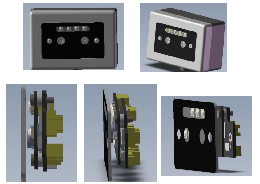
The AI vision algorithm module is assembled inside the product, and a cover plate needs to be attached to the top of the AI vision algorithm module to prevent water, dust and damage.

1. The cover plate and the module are installed directly
The top of the lens of the AI vision algorithm module and the top of the LED lamp bead are basically on the same horizontal plane. When installing the AI vision algorithm module, it is recommended that the lens on the AI vision algorithm module and the cover plate are as close as possible but not in contact, with a gap of ≤1mm.
The contact surface between the lens and the cover plate is shielded by light-shielding foam (thickness: 2~3mm) (foam is already standard when leaving the factory), and the light-shielding foam is close to the cover plate. The hole of the light-shielding foam is outside the visible area of the camera to avoid blocking the visible area. The opening area of the cover must also be outside the visible area of the camera to avoid blocking the visible area of the camera.
If the gap between the cover and the lens is large, the LED light will be reflected into the camera through the cover, causing the image to be overexposed and the portrait cannot be recognized normally.

2. Size of the cover window
When making the cover, it is necessary to leave a transparent window in the visible area of the camera and the irradiation area of the LED light, and the transparent light transmittance should reach 90% or more.
Based on the viewing angle of the camera and LED light, and taking into account the tolerance of mold opening and installation tolerance, it is recommended that the horizontal opening angle of the LED light be ≥90°; the horizontal opening angle of the camera be ≥60°, and the vertical opening angle of the two be ≥78° (as shown below). It is recommended that the cover plate be 2.5mm away from the light board, the lens opening diameter be 6mm, and the LED light hole diameter be 6.3mm, which can meet the requirement of not blocking the field of view.

3. Choice of cover
(1) Cover material: tempered glass or acrylic
(2) It is recommended to make the window of the white light LED part of the cover into a long strip. As shown in the figure, a light-diffusing film can be pasted on the back of the long strip window, or white light-transmitting ink can be sprayed when making the cover. To prevent glare caused by white light on
(3) The infrared light and camera window of the cover are transparent, and the light transmittance of the transparent part is ≥90% (850nm band)
(4) Cover thickness: 0.55mm~1.5mm, 1mm is recommended as the best
(5) Cover design reference
Assembly of shell and bracket
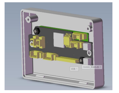
When the algorithm Al vision algorithm module is placed on the shell or bracket, it should be positioned to prevent movement when screwing, causing the center of the camera to deviate from the hole position and block the imaging.
The diameter of the through holes on both sides of the AI vision algorithm module is 2.2mm, and M2 screws are preferred.
After installation, the center of the camera should be aligned with the center of the housing or bracket through-hole to ensure that the camera imaging is not blocked. The algorithm AI vision algorithm module cannot be touched or squeezed by other structures to avoid short circuit or damage.
FAQ
- When in use, the sensor USB port must be connected to a 5V USB power supply
- The foam on both sides of the camera cannot be removed
- Chip heating is normal
