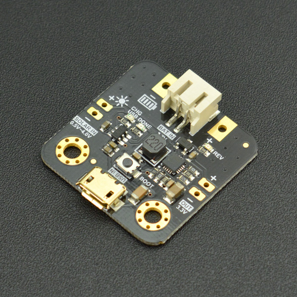
Solar Power Manager Series
Introduction
The DFRobot Solar Power Manager series are designed for IoT and renewable energy projects, providing safe and high-efficiency embedded solar power management modules for makers and application engineers. All modules in this series have MPPT (Maximum Power Point Tracking) to maximize solar energy conversion efficiency under various sunlight. A complete battery and power protection provide reliable power management for different types of solar projects.
Selection Guide
| Name | Solar Power Manager 1.0V | Solar Power Manager 5V V1.1 | Solar Power Manager Micro V1.0 ★ | Solar Power Manager For 12V Lead-Acid Battery V1.0 |
|---|---|---|---|---|
| SKU | DFR0535 | DFR0559 | DFR0579 | DFR0580 |
| Solar Power Management IC | LTC3652 | CN3065 | SPV1050 | CN3767 |
| Solar Input Voltage | 7V ~ 30V | 4.4V ~ 6V | 0.5V ~ 4V | 15V ~ 25V |
| Maximum Charge Current (Solar) | 2A (Solar/USB) | 900mA (Solar/USB) | 70mA (Solar)/100mA (USB) | 4A (Solar) |
| Topology | DC-DC Buck | Linear Regulator | DC-DC Boost | DC-DC Buck |
| Battery | 3.7V Lithium Battery | 3.7V Lithium Battery | 3.7V Lithium Battery | 12V Lead-Acid Battery |
| MPPT | 9V/12V/18V Optional | Fixed 5V | 75% Open Voltage | Fixed 18V |
| Battery Protections | Over Charge/Over Discharge/Over Current/Reverse Connection Protections | Over Charge/Over Discharge/Over Current/Reverse Connection Protections | Over Charge/Over Discharge/Reverse Connection Protections | Over Charge/Over Discharge/Reverse Connection Protections |
| Output Protections | Short Circuit/Over Current/Over Heat Protections | Short Circuit/Over Current Protections | Short Circuit/Over Current Protections | Short Circuit/Over Current/Over Heat Protections |
| USB Charge IN | Yes | Yes | Yes | No |
| USB OUT | 5V 1.5A | 5V 1A | No | 5V 2.5A X2 |
| Regulated OUT | Three Regulated Outputs 3.3V 1A;5V 1.5V;9V/12V 0.5A |
One Regulated Output 5V 1A |
One Regulated Output 3.3V 90mA |
Two Outputs 5V 5A; 12V 8A |
| Dimension | 78.0mm×68.0mm | 33.0mm×63.0mm | 30.0mm×30.0mm | 68.0mm×68.0mm |
| Features | A complete multifunction solar power management module. Applications: Small Solar Street Lamp, Solar Powered Robots For 9V/12V/18V Solar Panels within 20W |
A small and easy-to-use 5V solar power management module. Applications: Solar Power Bank, Solar Environment Monitors For 5V Solar Panels within 10W |
A micro power solar power management module for low-power sensors and controllers. Applications: Wireless Sensor Network, BLE iBecon For 1V/2V/3V Solar Panels within 0.5W |
Medium power solar management module for 12V lead-acid batteries. Applications: Street lighting, intelligent agriculture, environmental monitoring station For 18V Solar Panels within 100W |
Introduction
Solar Power Manager Micro is a micro power, high-efficiency solar power management module, designed for powering IoT based low-power wireless sensors or controllers with 1V~3V small size solar panels. Benefited from its extremely low power dissipation and MPPT (maximum power point tracking), the module is able to maximize the conversion efficiency of solar energy under weak sunlight. These features make low-power wireless devices charge-free and battery replacement-free possible by pure solar power.
The module employs a constant voltage ratio MPPT (Maximum Power Point Tracking) algorithm to maximize the output power of the solar panel under various sunlight. It can charge a 3.7V lipo battery through solar or USB, providing charge current up to 70mA or 100mA respectively. A 3.3V 90mA regulated output can handle burst current of most low-power wireless devices during transmitting or receiving. In low-power solar projects, lipo battery may suffer from the over-discharge problem when it is cloudy for days, or the capacity of the battery cannot meet the device’s need. The battery over-charge and over-discharge protections are designed to prevent such problems to extend battery life.
Features
- Constant voltage ratio MPPT algorithm, maximizing solar energy conversion
- Designed for 1V ~ 3V low voltage small solar panels, ultra low power design
- Solar/USB two charging methods
- Multiple protections extending battery life
Specifications
Micro Solar Power Management Module
- Solar Power Management IC: SPV1050
- Solar Input Voltage (SOLAR IN): 0.5V~4V
- Battery Input (BAT IN): 3.7V Lithium Battery
- Charge Current: 37mA@USB IN; 70mA@SOLAR IN
- Over-charge Protection Threshold: 4.2V
- Over-discharge Protection Threshold: 3.1V
- Regulated Power Supply: 3.3V 90mA @ BAT IN 3.7V
- Operating Current: <3 uA
- Protection Functions
- BAT IN: Over-discharge/Over-charge/Reverse Connection Protections
- OUT: Short Circuit/Over Current Protections
- Operation Temperature: -40℃~85℃
- Dimension: 30.0mm*30.0mm
Solar Panel 2V 160mA
- Nominal Voltage (VMP): 2V
- Nominal Current (IMP): 160mA
- Open Circuit Voltage (IOC): 2.4V
- Short Circuit Current (ISC): 190mA
- Solar Cell Material: Monocrystalline silicon
- Other Features: Waterproof, Oil Resistant and Corrosion Resistant
- Dimension: 50mm*50mm
Applications
- Wireless Sensor Network
- Bluetooth iBeacon
- Solar Powered Toys
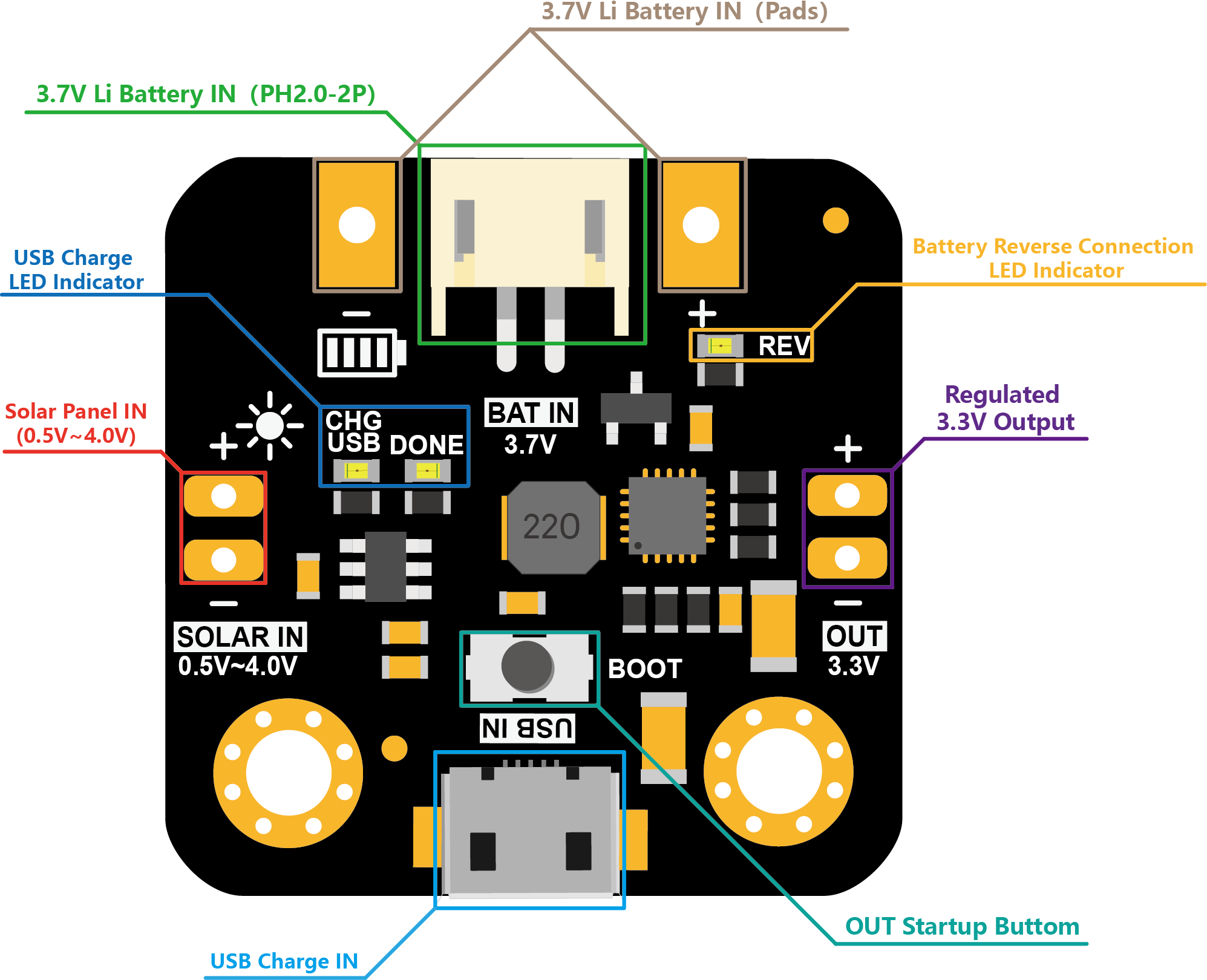
Board Overview
Quick Start
Solar Powered Low Power Wireless Sensors
- Connect a 3.7V lithium battery to BAT IN.
- Solder the 2V 160mA solar panel to SOLAR IN (pay attention to the negative and positive poles, the SOLAR IN DOES NOT has a reverse connection protection).
- Power the wireless sensor by soldering its power supply pins (usually marked as VCC and GND) to the positive (+) and negative (-) of OUT 3.3V respectively.
- Short press BOOT to activate the circuit to output 3.3V at OUT.
Attention
- When only the solar panel is connected without the battery, OUT DOES NOT have any load capacity. Please connect the battery.
- If SOLAR IN is not connected to the solar panel, OUT will be no output the first time the battery is installed or each time replaced. A short press of the BOOT button will short-circuit the positive pole of battery BAT IN and the SOLAR IN to activate the circuit to generate 3.3V at OUT.
- If the SOLAR IN has been connected to the solar panel and is placed in a sunny place (or use the flashlight of your smart phone), the circuit will be automatically activated. OUT will output 3.3V normally without the need to press BOOT button.
- OUT will be immediately shutdown when the output is short circuit or over-current. After troubleshooting, short press the BOOT button to reactivate the circuit and restore the output.
- The PH2.0-2P terminal and pads on the BAT IN are directly connected internally. The user can select one of the ways to connect the battery. |

Detailed Description
Maximum Power Point Tracking, MPPT
The MPPT (Maximum Power Point Tracking) can ensure the solar panel output power maintains at its maximum under different loads and sunlight, maximizing the conversion efficiency.
We can identify the short circuit current ISC and the open circuit voltage VOC from the cross points of the I/V curve (green) with x and y axis respectively. The ISC and VOC grow larger with the illumination increasing. With the output voltage VPANEL growing, the output current IPANEL gradually decreases and then jumps down after crosses a special point VMP, the maximum power voltage. By multiplying the voltage and current, which obviously results in power, and take the output voltage as the x axis, we obtain the P/V curve (blue). The output power PPANEL reaches its peak when the output voltage is at VMP. Although the maximum power increases with illumination, the VMP changes little. Therefore, we may approximately take the VMP as a constant for a specific solar panel under different illumination. This value is usually 70%~80% of the open circuit voltage VOC, i.e. VMP=(70% ~ 80%)*VOC.
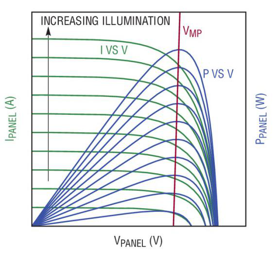
The ST SPV1050 micro solar power management chip used in this module uses a constant voltage ratio MPPT algorithm to control the output voltage of the solar panel about 75% of the open circuit voltage to maximize the output power of the solar panel.
Solar Panel Selection
The SOLAR IN port can be connected to any type of solar panel (amorphous silicon, polycrystalline silicon, monocrystalline silicon) with a nominal voltage of 1V ~ 3V. The 2V 160mA monocrystalline silicon solar panel (attached in the package) can meet the power requirements of most low-power wireless sensors. If a folding solar panel is needed for outdoor sports or wearable devices, one or two (in serial) DFRobot 1.5V Flexible Solar Panel can be used instead.
The maximum charge current the module can achieve for the battery is related to the input voltage of SOLAR IN. For a 1V input, the maximum charge current (flowing into the battery) is 13mA; for 2V, it is 30mA; for 3V, it is 50mA and achieves maximum 70mA at 4V. Basically, the greater the input voltage, the greater the maximum charge current that can be reached.
Warning
The absolute maximum input voltage of SOLAR IN is BAT IN + 0.3V. For fully charged 3.7V lipo battery, this results in 4.5V. Keep the SOLAR IN input voltage below 4V or the module will be permanent damage.
Battery Selection
The module can use a regular 3.7V lithium battery. The maximum allowable charging current of these batteries are related to the battery's charge ratio and capacity. To ensure the safety of the battery, it is necessary to pay attention to the battery's nominal maximum charging current. Generally, the manufacturers will specify the charging rate and capacity. The formula: ’’’maximum allowable charging current (mA) = battery capacity (mAH) * charging rate (C) ’’’ can be used to evaluate whether the maximum allowable charging current of the used lithium battery is greater than 100 mA (with USB IN for example). The charge rate of a common lithium battery is 1C, which require a capacity of 100mAh or more. The power type (aircraft model) lithium battery generally has a higher charge/discharge rate, so that a smaller-capacity battery can be used. However, most of the lipo batteries are over 100mAh. It is seldom meet such charge current issue for this module.
LED Indicators
There are two types of LED indicators indicating the operation status of different parts of the module:
- Reverse connection LED indicator: when the battery is reverse connected at the BAT IN, the corresponding orange LED REV turns ON, informing the user a reverse connection error.

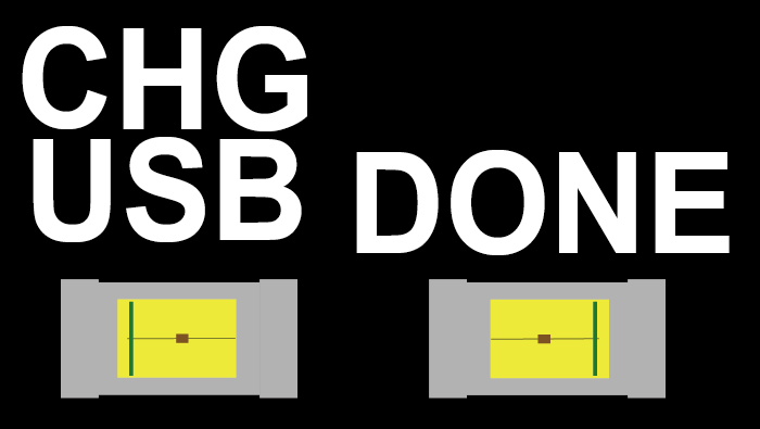
- USB charge LED indicators: when using the USB to charge the battery, the CHG USB (red) turns on. If the battery is fully charged, the CHG USB turns off and the DONE (green) turns on instead. If no battery is connected (USB IN connected), CHG USB will flash and DONE turns on.
Solar Charge Indicator
This module is used for low-power applications. In order to further improve efficiency and reduce self-dissipation, there is no charging LED indicator when using SOLAR IN. As long as SOLAR IN is input 0.5V~4V voltage, the module will charge the battery and automatically stop when fully charged. |
Protection Functions
-
Reverse connection protection: On the BAT IN, the reverse connection protection circuit prevents the reverse voltage from damaging the module and REV will turn on to inform the user.
-
Regulated output protection: OUT has short-circuit/overcurrent protection. When the output current exceeds a certain threshold (related to BAT IN and SOLAR IN voltage, but no more than 200mA) due to overload or short circuit, the output will be turned off, protecting the circuit from being damaged. After troubleshooting, short press the BOOT button to resume output.
-
Over-charge and Over-discharge protection: The charge-cutoff (over-charge protection) voltage of the module is 4.2V, protecting the battery from over-charge. When the battery is discharged to 3.1V, the BAT IN will be disconnected internally to prevent the battery from over-discharge.
About Battery Protections
Overcharging or overdischarging can cause great damage to the battery and greatly reduce the battery life. Lithium battery chargers generally have a constant voltage charge phase to prevent the battery from overcharge. However, the over-discharge protection generally depends on the protection circuit packaged with the battery. If the battery does not has any protection, and the devices do not have any low-voltage indication or lockout, the battery is most likely to encounter the problem of over-discharge. Users are likely to be aware of charging the battery until the device is powered down due to low battery voltage. Howerver, under such conditions, the battery has already been severely over-discharged or even permanently damaged. In solar power projects, the whole system is often unattended. Lipo battery may suffer from the over-discharge problem when it is cloudy for days, or the capacity of battery cannot meet the device’s need. The over-discharge protection plays an important role in such a situation to extend battery life.
Application Examples
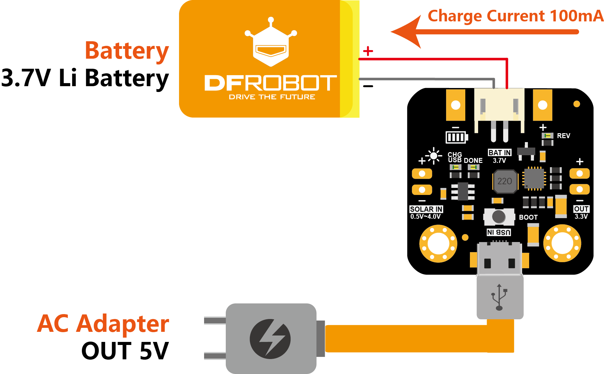
Charge a Small 3.7V Lipo Battery with USB
The module can provide up to 100mA charge current for 3.7V lithium batteries with USB IN. The charging current for many lithium battery chargers or charging modules is 2A, 1A or 500mA, which has already exceeded the maximum allowable charging current for a small 3.7V lithium battery below 500mAh (assume 1C charge rate). This module can provide a safe charging current for such small-capacity lithium batteries. Of course, the actual charging time is related to the battery capacity. The larger the battery capacity is, the longer the charging time is.
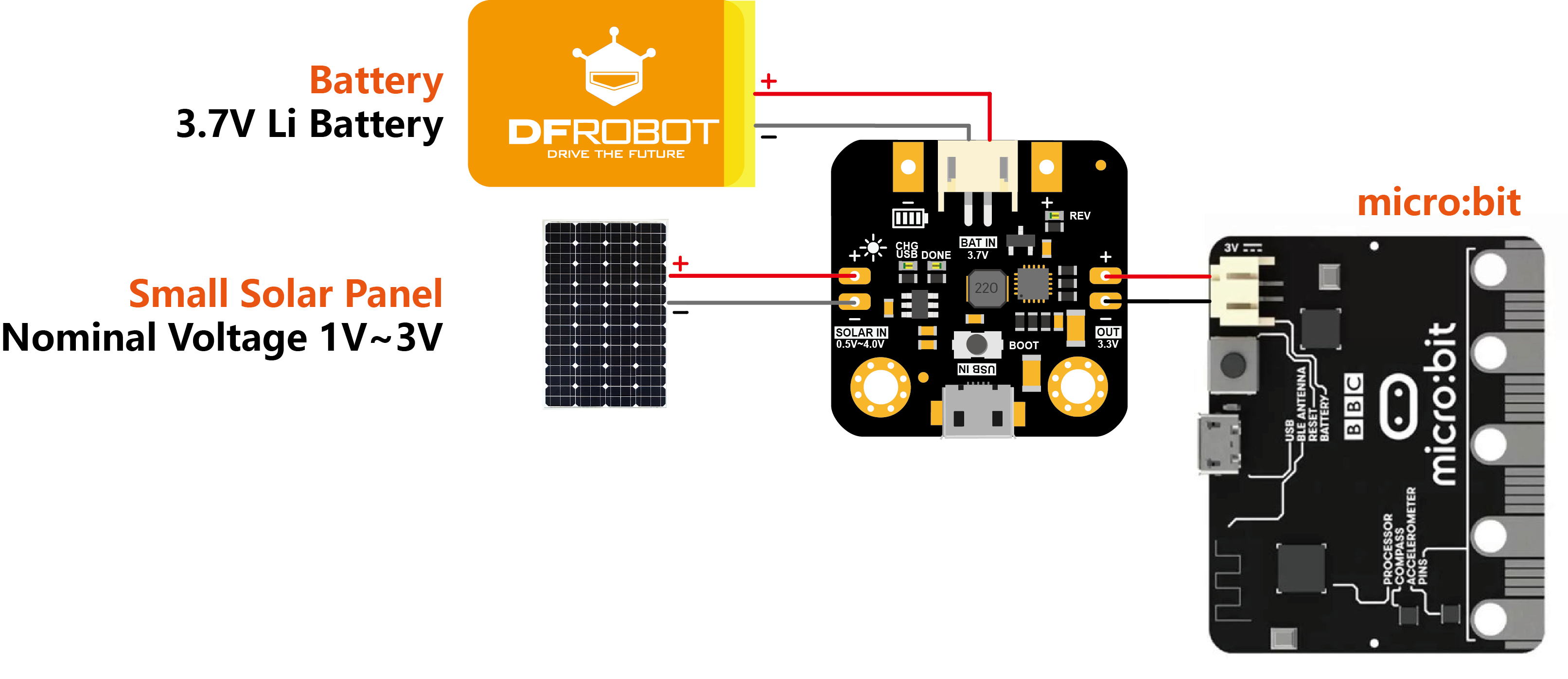
Power micro:bit with a 3.7V Lipo Battery and Solar Panel
According to the official specification of micro:bit, the battery port supports a maximum voltage of 3.3V. This makes the commonly used 3.7V lipo battery (full voltage up to 4.2V) unavailable. Solar Power Manager Micro can regulate the battery input to 3.3V, so that users can safely power micro:bit with a 3.7V lipo battery. The module not only serves as an LDO (Low-dropout linear regulator), but also serves as a battery protection circuit and charger. More importantly, as introduced above, the module can efficiently collect solar energy, extend battery life, and even fully power micro:bit with only solar power, without the need of charging with USB.
When only powerd by LIR2032 with all the LEDs and the Bluetooth of the micro:bit turn on, it can run about 1.5 hours. If only a 100mAh 3.7V lipo battery is used, the battery life will be extended to about 4h. However, if supplemented with solar panels, depending on the rated power of the solar panel and local light intensity, the battery life can be further extended. !
Power Firebeetle with Solar Panel
DFRobot FireBeetle series is abundant in peripherals and I/O pins. The wifi, Bluetooth as well as its low power features make it ideal for IoT projects. For an outdoor distributed wireless sensor based on FireBeetle, the entire system is powered by the battery. To make it last for a longer time or even battery replace free (or charged free), power such as wireless sensor node with solar will be the best candidate. By using the PH2.0-2P terminal and lead-out pads, it is able to power FireBeetle with only battery at nights and with both battery and solar at days (excessive solar energy will be stored in the battery). This can greatly cut down maintenance cost, especially in the configuration of ten or even dozens of nodes.

FAQ
For any questions, advice or cool ideas to share, please visit the DFRobot Forum.
