Introduction
The main function of this TC01 non-contact 16x4 pixel infrared temperature sensor is to realize remote temperature detection via non-contact 16x4 pixel infrared. It can detect the environment temperature, and its 16x4 pixels support producing temperature figure of 64 pixels. The sensor adopts metal crust, which is waterproof, dustproof and ensures high anti-interference even in varieties of complex scenarios. The standard Modbus-RTU industrial protocol RS485 interface is adopted. So that it is compatible with a variety of industrial personal computer.
It can be widely applied to applications like high-precision contactless temperature testing, temperature scanners, intrusion/motion detection, status detection/human positioning and so on.
Specification
- Operating Voltage: Operating Voltage: 9-24V DC
- Rated Power: 0.1W
- Operating Temperature: -40℃-85℃
- Temperature Detection Range: -20℃-300℃
- Precision: ±1℃~±5.5℃
- Infrared Array: 16x4
- FOV: 60°x 16°
- sampling rate:8Hz
- Protection Level: IP65
- Communication Interface: RS485
- Communication Protocol: Modbus-RTU
- Probe Diameter: 0.606inch / 15.4mm
- Probe Length: 3.110inch / 79mm
- Cable Length: 1.5m
- Cable Interface: stripped tin-plating wire interface
Overview

| Num | Wire Color | Description |
|---|---|---|
| 1 | White | VCC(+) |
| 2 | Black | GND(-) |
| 3 | Orange | RS485-A |
| 4 | Brown | RS485-B |
Pixel Arrangement Schematic
NOTE: The infrared array has 16x4 pixels in all.
Description about FOV and Distance
The field-of-view angle of the sensor is 60°x 16°. The maximum distance between the target under test and the measuring head is depended on the size of the target being measured and the optical characteristics of the infrared thermometer.
![]()
Measurement Accuracy Change

Annotation:
To-Measure temperature
Ta-ambient temperature
NOTE:
- All precision specifications are only applicable to stable temperature conditions.
- Accuracy is only effective if the object is fully covered by the sensor's field-of-view angle.
- The precision parameters shown in the figure are the accuracy of the four center pixels of the product, and the accuracy of the remaining pixels depends on the uniformity declaration.
- Due to long-term (year) drift, the temperature of the measured object near room temperature may have an additional measurement deviation of ±3°C.
Modbus -RTU Register Table
Description: support Modbus function codes: 0x03, 0x06, 0x10
Tutorial
Requirements
-
Hardware
- Leonardo with Xbee Socket (Arduino Compatible) x 1
- RS485 Shield for Arduino x 1
- 9v- 24v External Power Supply x1
- TC01 Non_contact 16x4 Pixel Infrared Temperature Sensor x1
-
Software
- Arduino IDE
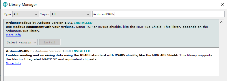
- Download and install the [ArduinoModbus] and [ArduinoRS485] in Library Manager(Ctrl+Shift+I).
(About how to install the library?)

Connection Diagram

Sample Code
#include <ArduinoModbus.h>
#include <ArduinoRS485.h>

#define baudRate 19200
#define addr 0x0A

float To[64]= {0.0};
float Ta= 0.0;

void getTa()
{
    if (!ModbusRTUClient.requestFrom(addr, HOLDING_REGISTERS, 0x45,1))
    {
        Serial.println("error: ");
        Serial.println(ModbusRTUClient.lastError());
    }
    else
    {
        Ta= ModbusRTUClient.read()/10.0;
    }
    delay(100);
}

void getTo()
{
  for(uint8_t row=0;row<4;row++)
  {
    if (!ModbusRTUClient.requestFrom(addr, HOLDING_REGISTERS, 0x05+(row*0x10),0x10))
    {
        Serial.print("error: ");
        Serial.println(row);
        Serial.println(ModbusRTUClient.lastError());
    }
    else
    {
        for(uint8_t i=0; i<16; i++)
        {
            To[row*16+i]=ModbusRTUClient.read()/10.0;
        }
    }
    delay(100);
  }
}

void setup() {
    Serial.begin(baudRate);
    ModbusRTUClient.begin(baudRate);
}

void loop() {

    /**********Ta*****************/
    getTa();
    Serial.println("======== Ta ========");
    Serial.println(Ta,1);

    /**********TO**********************/
    getTo();
    Serial.println("======== To ========");
    for(uint8_t i=0; i<64; i++)
    {
        Serial.print(To[i],1);
        Serial.print("  ");
        if((i+1)%16==0)Serial.println();
    }
    delay(100);
}
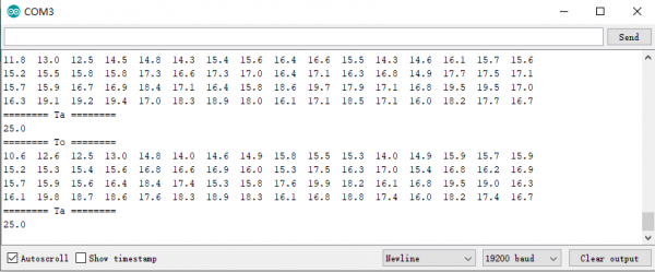
Expected Results

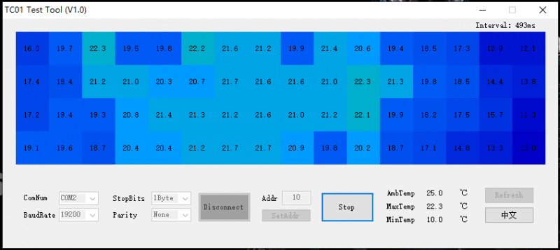
Visual Testing Software
Connection Diagram
Please refer to the hardware connection above(but there is no need to install library).
*
This code realizes the function to transform Leonardo USB to 485. And you can also test it with other DF USB to 485 tools.
*/
void setup() {
  Serial.begin(19200); //Initializing Serial (i.e. USB serial)
  Serial1.begin(19200);//Initializing Serial
}
void loop() {
  while (Serial1.available()) {
    Serial.write(Serial1.read());//If Serial1 receives data, then Serial will output it.
  }
  while (Serial.available()) {
    Serial1.write(Serial.read());//If Serial receives data, then Serial1 will output it.
  }
  delay(1);//Short delay to avoid USB-COM instability
}
Host Computer Software
Click to download TC01 measurement tool.

FAQ
For any questions, advice or cool ideas to share, please visit the DFRobot Forum
