Introduction: DFR0017 V2 Relay
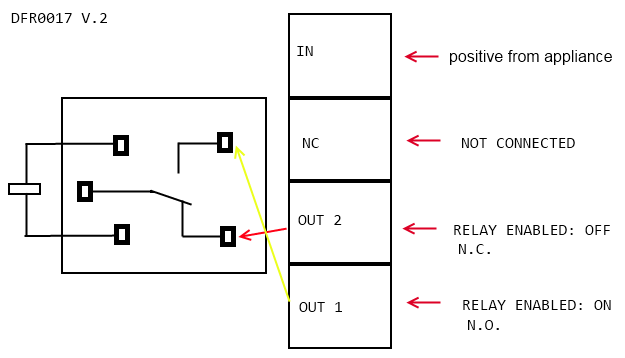
In this tutorial we will show you how to use the DFR0017 V2 Relay. The diagrams below should help you understand the layout of the relay board.
The relay in use is: JQC-3FF
Relay board layout
There are a total of 7 pins on the relay board. On the Arduino side there is:
- Signal
- Vcc
- Ground
On the appliance side there is:
- In: input positive wire from appliance
- NC: not connected
- Out2: Normally closed, which means that when the relay is off (a digital low "0" is received from Arduino) the device is ON
- Out1: Normally open, which means that when the relay is on (a digital high "1" is received from Arduino) the device is ON.
So, using Out1 a "1" will turn on the device and a "0" will turn off the device.

WARNING: Please be vary carful not to play with live circuits! 120V or 220V should not be taken lightly. Make sure the appliance to be tinckered with is unplugged from mains. (DO NOT CONNECT IT TO THE WALL WHILE MESSING WITH THE CABLE!)
Plugging in an appliance
We will use "out1" for our example, using "out2" will simply reverse the logic, as explained above.
We recommend using a swappable cable to do this with, as using a relay requires you to perform some minor surgery on the appliance's cable.
To plug in an appliance such as a lamp:
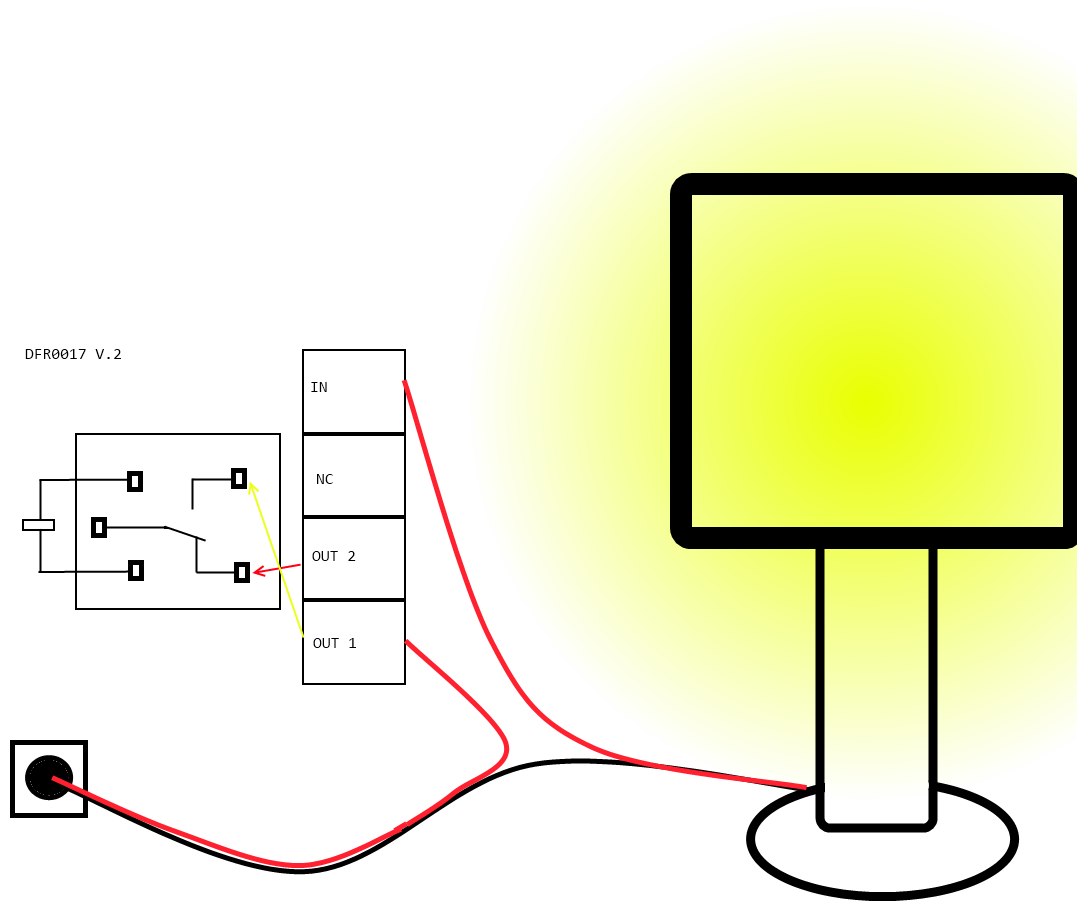
Cut and strip a portion of the positive wire so that you end up with two ends of the wire as shown in Figure 2.
The relay should have the positive wire of the device being used connected to "IN" and to "Out 1" as shown in figure 2, and any digital signal pin on the arduino end (For example pin 13).
Sending a digital high or a "1" will trigger the relay. Sending a digital low or "0" will disable the relay.
