Introduction
This is an uninterruptable power supply shield for Raspberry Pi Zero series, and also compatible with Pi 2/3/A+ . It can provide steady power source to Raspberry Pi for an extended period of time when the system is powered off, by which to avoid system damage and assure safe shut down. In addition, the product can be used to supply power for the applications requiring mobility such as, Raspberry Pi camera, tablet PC, field data collection system.
A MAX17043 fuel gauge is adopted in this product for accurate power detection. Besides, we also employed an on-board microcontroller (MCU) for data processing. In this way, Raspberry Pi board is able to directly get information of power capacity and battery voltage via I2C communication. 5 on-board LEDs on the shield could show the status of the battery power visually without programming.
We adopted an excellent power management solution in this Raspberry Pi UPS HAT. Over 90% power conversion efficiency and non-dioded design make the shield able to keep low heating temperature even under continuous high load operation of Raspberry Pi.
 Notes:
- 3.7V Lithium Battery is not included in the package due to transportation constraints.
- Please use 3.7V Lithium Battery that meets standard specification.
- Please note that there would be a certain degree of heating in the power source area of the product during operation, you can never be too careful in using.
Specification
- Supply Voltage: 4.5~5.5V
- Supply Current: (recommend using adapter with power of 2A and above)
- Power Supply Interface: Micro-USB
- Maximum Charge Current: 1.6A
- Battery Interface: PH2.0-2P or solderable contact
- Battery: 3.7 Lithium Battery
- Output Voltage: 5V
- Maximum Output Current: 2A
- Main-Board: Raspberry Pi B/B+/2B/3B/3B+ and subsequent version
- Communication Interface: I2C
- Dimension: 65x30mm/2.56x1.18”
- Mounting Hole Size: 58x23mm/2.83x0.91”
- Operating Temperature: -40℃~85℃
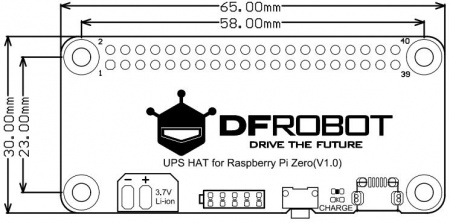
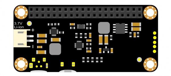
Pinout
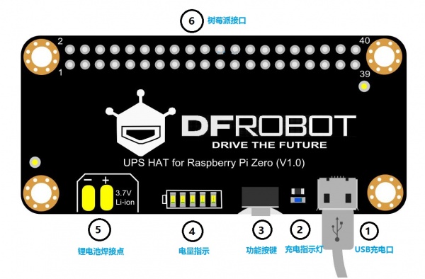
| Serial Number | Function Description | Status Description |
|---|---|---|
| 1 | USB charge interface | Charge by 5V DC |
| 2 | Charging Indicator | ON: in charging/ Blinking: battery is not detected/ OFF: uncharged |
| 3 | Function Key | Refer to Firmware version update and function description |
| 4 | Electric Quantity Indication | Indicating Present electric quantity |
| 5 | Li-ion Battery Solder Contact | Solder Li-on Battery |
| 6 | Raspberry Pi 40Pin Socket | Connect Raspberry Pi |
LEDs vs Electric Quantity
| Electric Quantity(EQ) | LEDs Status(uncharged) | LEDs Status(in charging) |
|---|---|---|
| EQ<10% | The first LED flashes slowly(about at a frequency of 3Hz) | The first LED flashes quickly(about at a frequency of 6Hz) |
| 10%≤EQ<20% | The first LED is on | The first LED flashes quickly(about at a frequancy of 6Hz) |
| 20%≤EQ<40% | The first two LEDs are on | The first LED is on, and the second LED flashes quickly (about at a frequency of 6Hz) |
| 40%≤EQ<60% | The first three LEDs are on | The first two LEDs is on, and the third LED flashes quickly(about at a frequency of 6Hz) |
| 60%≤EQ<80% | The first four LEDs are on | The first three LEDs is on, and the fourth LED flashes quickly(about at a frequency of 6Hz) |
| EQ≥80% | 5 LEDs are on | The first four LEDs is on, and the fifth LED flashes quickly(about at a frequency of 6Hz) |
Firmware Version Update and Function Description
| Version | Date | Button Description | Others |
|---|---|---|---|
| V1.0 | 2018/11/19 | Display the current battery power for 10s | when the battery power is lower than 10%, the 5V power output will be cut off automatically |
| V1.1 | 2019/09/20 | 1. Short-press to display the current battery power for 3s. 2. Long-press(>2s) to turn on/off 5V power output. | when the battery power is lower than 5%, the 5V power output will be cut off automatically. Need to be switched on manually when the battery power goes up to 7%. |
| V1.2 | 2020/12/21 | 1. Short-press to display the current battery power for 3s. 2. Long-press(>2s) to turn on/off 5V power output. | When the battery power is lower than 5%, the 5V power output will be cut off automatically. Plug in the charger, when the battery power increases to 7%, the 5V power supply will restart automatically |
| V1.3 | 2021/03/02 | No change to product function | Fixed some stability problems based on V1.2 |
Register Description
| Register | Name | R/W | Data Range | Default Value | Description |
|---|---|---|---|---|---|
| 0×00 | Device address | R/W | 1-127 | 0×10 | I2C Slave address. The default address is 0×10. If the address is changed, the new address will be valid after repowering the module |
| 0×01 | PID | R | 0×DF | Product ID | |
| 0×02 | VERSION | R | Factory Firmware Version Number | Firmware Version Check(0x10 for V1.0, 0x11 for V1.1) | |
| 0×03 | Voltage Value Register high-order bits | R | 0×00 | LSB is 1.25mV, and combine with voltage value register high-order bits into a 12 bits voltage value. VCELL_H=0×0A, VCELL_L=0×50, VCELL=0×0A50*1.25=3300mV | |
| 0×04 | Voltage Value Register low-order bits | R | 0×00 | LSB is 1.25mV, and combine with voltage value register high-order bits into a 12 bits voltage value. VCELL_H=0×0A, VCELL_L=0×50, VCELL=0×0A50*1.25=3300mV | |
| 0×05 | Electric Quantity High-order bits register | R | 0×00 | LSB is 0.003906% of Electric Quantity. For example: SOC_H=0×3C, SOC_L=0×FF, SOC=0×3CFF*0.003906≈60.99% | |
| 0×06 | Electric Quantity low-order bits register | R | 0×00 | LSB is 0.003906% of Electric Quantity. For example: SOC_H=0×3C, SOC_L=0×FF, SOC=0×3CFF*0.003906≈60.99% |
Tutorial
- Connect with Raspberry Pi by 40Pin
- Read electric quantity through Raspberry Pi
How To Enable Raspberry Pi I2c Interface?
Normally, Raspberry Pi’s I2C interface is default to be disabled. Users need to enable it manually to access the related data of DFRobot Raspberry Pi UPS HAT(such as battery capacity and set turn-on time) via I2C bus.
- Enable I2C Interface
Input command to the terminal: sudo raspi-config, select [Interfacing Options](or[Advanced Options])->[I2C]->[Yes]->[OK]
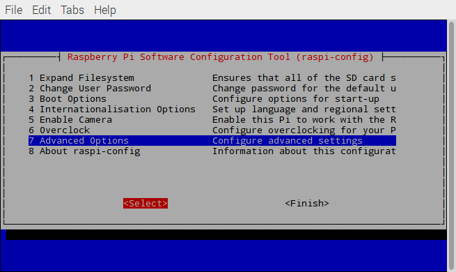
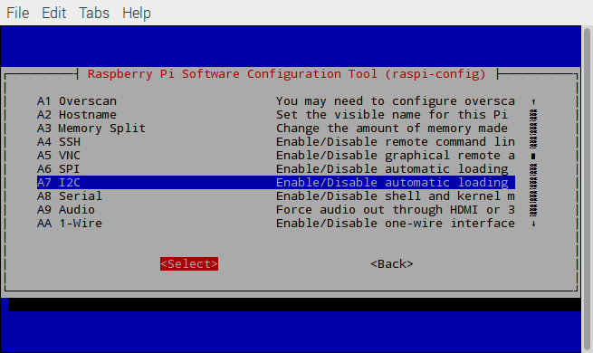
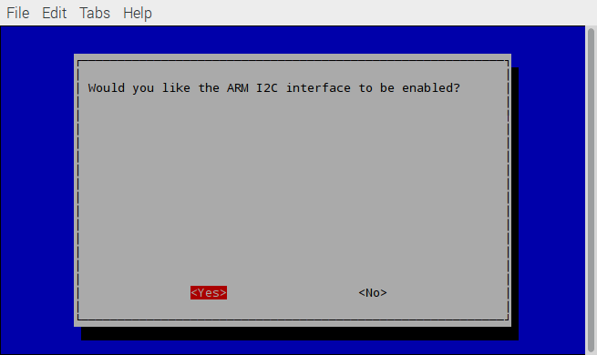
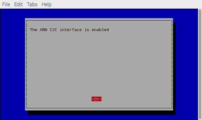
Reboot Raspberry Pi after finishing configuration(command: reboot)
- Check if I2C interface configuration is ok.
Check if I2C interface configuration is ok by Ismod, seen as below.
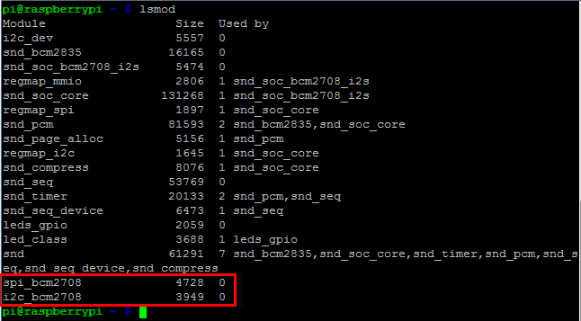
- Install tool to test I2C device
Command:
sudo apt-get install i2c-tools
Test if the installation is ok:
sudo i2cdetect -y l

If a problem like this appeared:

Then change raspi-blacklist.conf configuration, raspi-blacklist.conf is under /etc/modprobe.d/ directory, input command:
sudo nano /etc/modprobe.d/raspi-blacklist.conf
Add “#” to i2c device driver, such as:#blacklist i2c-bcm2835. Now I2C interface is enabled.
Check UPS Electric Quantity
- Create a script
Create ups.py file, and input the following the content:
import smbus
addr=0x10 #ups i2c address
bus=smbus.SMBus(1) #i2c-1
vcellH=bus.read_byte_data(addr,0x03)
vcellL=bus.read_byte_data(addr,0x04)
socH=bus.read_byte_data(addr,0x05)
socL=bus.read_byte_data(addr,0x06)

capacity=(((vcellH&0x0F)<<8)+vcellL)*1.25 #capacity
electricity=((socH<<8)+socL)*0.003906 #current electric quantity percentage

print("capacity=%dmV"%capacity)
print("electricity percentage=%.2f"%electricity)
- Run the script
Input python3 ups.py to the terminal to check the electric quantity information.
FAQ
| Q&A | Some general Arduino Problems/FAQ/Tips |
|---|---|
| A | For any questions, advice or cool ideas to share, please visit the DFRobot Forum. |
