Introduction
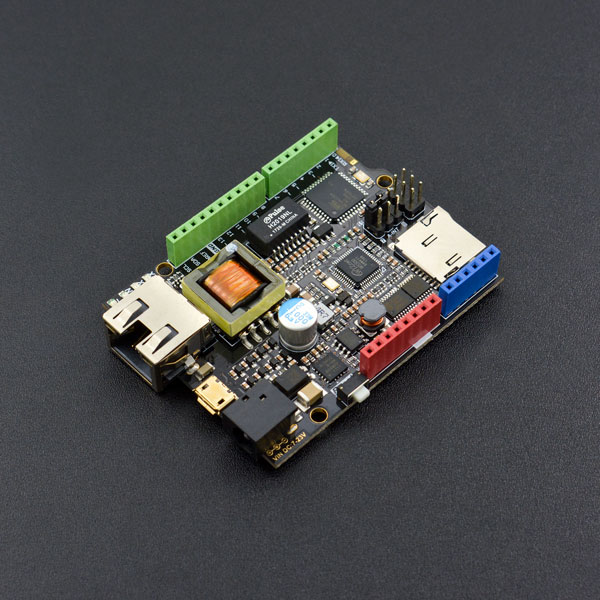
The W5500 Ethernet with POE IOT Board is the newest member of the DFRobot Ethernet family. Based on the ATmega32u4 and W5500 Ethernet chip, this board offers the same footprint as an Arduino Leonardo board, as well as being compatible with most Arduino shields and sensors, making it well suitable for many kinds of IOT applications. Different from the previous W5200 shield, this W5500 mainboard highlights its performance with the POE power supply and WOL mode integrated on the board.
Compliant with IEEE 802.3af standard and POE power supply agreement, the W5500 Ethernet mainboard for Arduino comes with onboard POE voltage-stablized circuit, external power voltage-stablized circuit, SD card circuit, and Leonardo unit-controlling circuit. The 4 layers wiring design and compact layout solved the previous space waste problem caused by the stackable design of Shield + Arduino. So, this board is small in size but with more powerful functions.
What's more, to ensure the system reliability in power changing, we adopt more intelligent and professional PD power chip, which enables all the onboard systems to work properly under all sorts of complicated environments.
What is a W5500 chip?
The W5500 chip is a Hardwired TCP/IP embedded Ethernet controller that provides
easier Internet connection to embedded systems. W5500 enables users to have the
Internet connectivity in their applications just by using the single chip in which
TCP/IP stack, 10/100 Ethernet MAC and PHY embedded.
WIZnet‘s Hardwired TCP/IP is the market-proven technology that supports TCP, UDP,
IPv4, ICMP, ARP, IGMP, and PPPoE protocols. W5500 embeds the 32Kbyte internal
memory buffer for the Ethernet packet processing. If you use W5500, you can
implement the Ethernet application just by adding the simple socket program. It’s
faster and easier way rather than using any other Embedded Ethernet solution. Users
can use 8 independent hardware sockets simultaneously.
SPI (Serial Peripheral Interface) is provided for easy integration with the external
MCU. The W5500’s SPI supports 80 MHz speed and new efficient SPI protocol for the
high speed network communication. In order to reduce power consumption of the
system, W5500 provides WOL (Wake on LAN) and power down mode.
Specification
- Microcontroller: Atmel Atmega32u4 (Arduino Leonardo)
- External Input Voltage Range (recommended): 7V~20V DC
- External Input Voltage Range (limit): 6-23V
- POE Input Voltage: 48V AC/DC (802.3af standard PD device)
- Digital I/O Pins: 20
- Analog I/O Pins: 6
- DC Current per I/O Pin: 40 mA
- Flash Memory: 32 KB (ATmega32u4) (4KB used by bootloader)
- SRAM: 2 KB (ATmega32u4)
- EEPROM: 1 KB (ATmega32u4)
- Clock Speed: 16 MHz
- PHY: WIZnet W5500
- PHY Clock Speed: 25MHz
- Dimension: 73.5 x 53.5x15mm
Pinout Diagram
We recommend that you remove the jumper caps if you don't need to use the W5500 reset and interrupt functions, or pins 7, 8, 11 or 12 may not function properly. 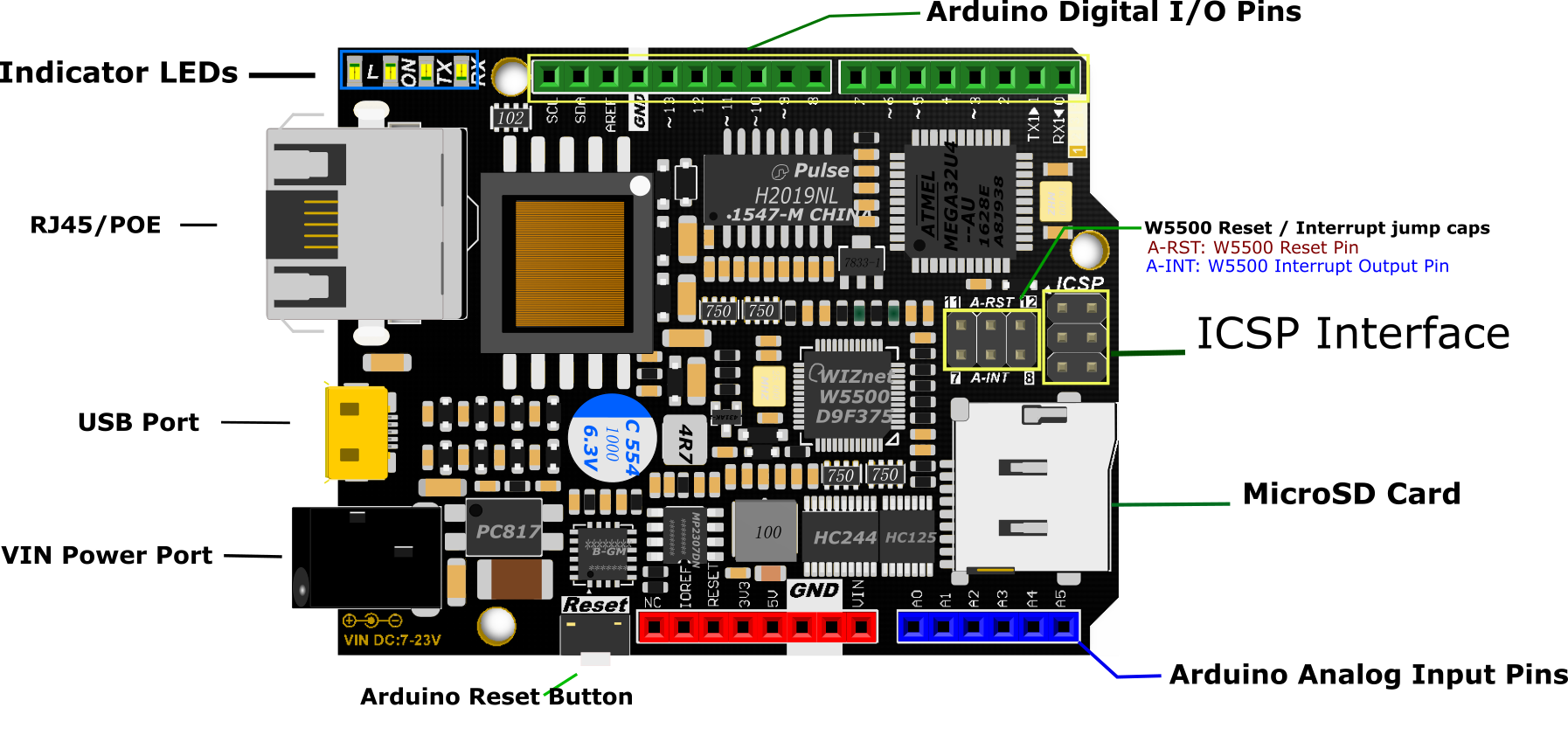
Tutorial
Preparation
You will need:
- W5500 Ethernet with POE Mainboard
- Micro USB cable
- PC
- RJ45 network cable
Step 1: Connections
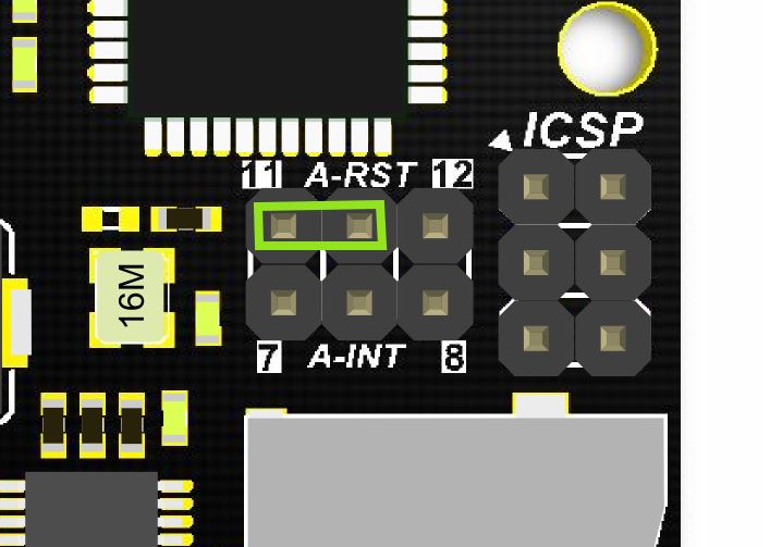
Connect W5500 Reset pins: Connect A-RST pin to D11. (Default: Connected)
Step 2: Library
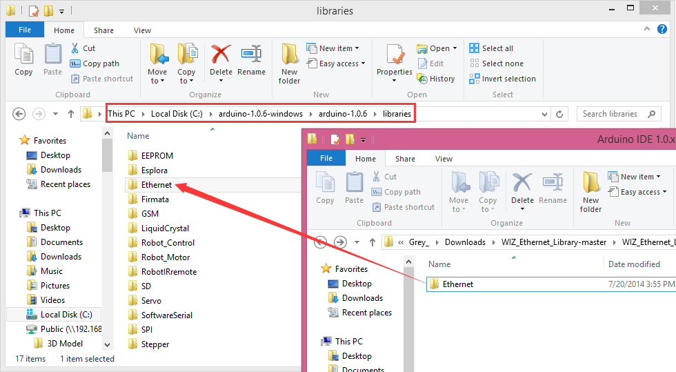
- Download the W5500 Ethernet library here
- Replace the existing Ethernet library according to your Arduino IDE version:
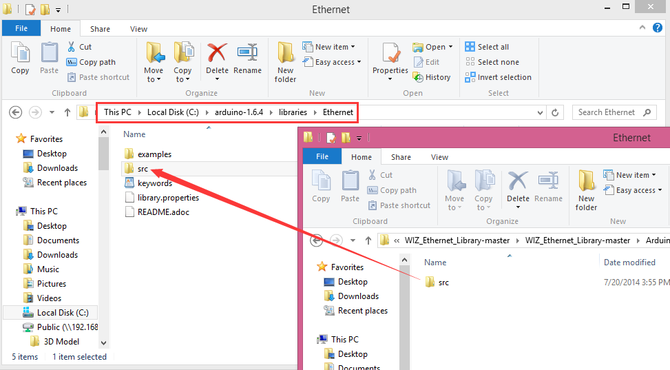
| NOTE: Good news! You can use arduino IDE v1.7 from Arduino.org which has "Ethernet 2" library, which works with this board. It means you don't have to download any modded libraries. Thank for the Vladimir Akopyan comments. Welcome share your projects and comments on the Disqus. |
Step 3: Pin Definitions
Note: These parts should be declared at the beginning of the sketch.
1. Define W5500 SPI “SS” pin and “Reset” Pin:
#define SS     10U    //D10----- SS
#define RST    11U    //D11----- Reset
2. Setup function
void setup() {
pinMode(SS, OUTPUT);
pinMode(RST, OUTPUT);
digitalWrite(SS, LOW);
digitalWrite(RST,HIGH);  //Reset
delay(200);
digitalWrite(RST,LOW);
delay(200);
digitalWrite(RST,HIGH);
delay(200);              //Wait W5500
Example
Open Arduino IDE, Select Boards -->Arduino Leonardo and COM port
/*  Web Server

 A simple web server that shows the value of the analog input pins.
 using an Arduino Wiznet Ethernet shield.

 Circuit:
 * Ethernet shield attached to pins 10, 11, 12, 13
 * Analog inputs attached to pins A0 through A5 (optional)

 created 18 Dec 2009
 by David A. Mellis
 modified 9 Apr 2012
 by Tom Igoe

 */
#include <SPI.h>
#include <Ethernet.h>
#define SS     10U    //D10 ---- SS
#define RST    11U    //D11 -----Reset

// Enter a MAC address and IP address for your controller below.
// The IP address will be dependent on your local network:

byte mac[] = {
  0xDE, 0xAD, 0xBE, 0xEF, 0xFE, 0xED
};

IPAddress ip(192, 168, 1, 177);

// Initialize the Ethernet server library
// with the IP address and port you want to use
// (port 80 is default for HTTP):

EthernetServer server(80);

void setup() {
  pinMode(SS, OUTPUT);
  pinMode(RST, OUTPUT);
  digitalWrite(SS, LOW);
  digitalWrite(RST, HIGH); //Reset
  delay(200);
  digitalWrite(RST, LOW);
  delay(200);
  digitalWrite(RST, HIGH);
  delay(200);              //Wait W5500
  //Open serial communications and wait for port to open :
  Serial.begin(9600);
  //while (!Serial) {
  //  ; // wait for serial port to connect. Needed for Leonardo only
  //}
  delay(1000);
  // start the Ethernet connection and the server:
  Ethernet.begin(mac, ip);
  server.begin();
  //Serial.print("server is at ");
  //Serial.println(Ethernet.localIP());
}

void loop() {
  // listen for incoming clients
  EthernetClient client = server.available();
  if (client) {
    //Serial.println("new client");
    // an http request ends with a blank line
    boolean currentLineIsBlank = true;
    while (client.connected()) {
      if (client.available()) {
        char c = client.read();
        Serial.write(c);
        // if you've gotten to the end of the line (received a newline
        // character) and the line is blank, the http request has ended,
        // so you can send a reply
        if (c == '\n' && currentLineIsBlank) {
          // send a standard http response header
          client.println("HTTP/1.1 200 OK");
          client.println("Content-Type: text/html");

          // the connection will be closed after completion of the response
          client.println("Connection: close");
          client.println("Refresh: 5");  // refresh the page automatically every 5 sec
          client.println();
          client.println("<!DOCTYPE HTML>");
          client.println("<html>");
          // output the value of each analog input pin
          for (int analogChannel = 0; analogChannel < 6; analogChannel++) {
            int sensorReading = analogRead(analogChannel);
            client.print("analog input ");
            client.print(analogChannel);
            client.print(" is ");
            client.print(sensorReading);
            client.println("<br />");
          }
          client.println("</html>");
          break;
        }
        if (c == '\n') {
          // you're starting a new line
          currentLineIsBlank = true;
        }
        else if (c != '\r') {
          // you've gotten a character on the current line
          currentLineIsBlank = false;
        }
      }
    }
    // give the web browser time to receive the data
    delay(1);
    // close the connection:
    client.stop();
    //Serial.println("client disconnected");
  }
}
Check that it works
Open the Arduino Serial Monitor to initialize the setup and you will see some information about the connection processing. Open your browser, input the IP address and you should get see data of 5 virtual analog pins:
image:DFR0342_Open serial first.png|Open the Serial Monitor first DFR0342_Browser.jpg|W5500 Ethernet webserver
| NOTE: If you want to skip the serial monitor step, you can comment out the lines waiting for !serial, and add a line: delay(2000); to ensure that initialization has finished. |
Serial.begin(9600);
delay(2000);
//  while (!Serial) {
//    ; // wait for serial port to connect. Needed for Leonardo only
//  }
POE Power Supply
This board supports POE power supply, so it doesn’t need any other power source if you use an active ethernet connection. For more information please check: POE (Power Over Ethernet)Wikipedia
FAQ
| Q&A | Some general Arduino Problems/FAQ/Tips |
|---|---|
| Q | How to set the IP address? |
| A | Open your Network connection properties, and check the IPv4 Address and Gateway. The first three numbers should be set as same as on your board. The last number can be any number between 0-255, as long as it is not occupied by any other devices. 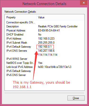 |
| Q | About Old Version Library |
| A | The Ethernet library that comes along with Arduino IDE is for W5100 Ethernet shield, which is not compatible with W5500. Hence that you need to replace this library with the new one as instructed. |
| Q | How to use the onboard micro-SD card slot? |
| A | Use it as the normal one using Arduino SD library is ok. Note that because the W5100 and SD card share the SPI bus, only one can be active at a time. For more, please check on Arduino, Arduino Ethernet Shield. |
More
- V1.0 Recource Download
- V2.0 Resource Download
