Introduction
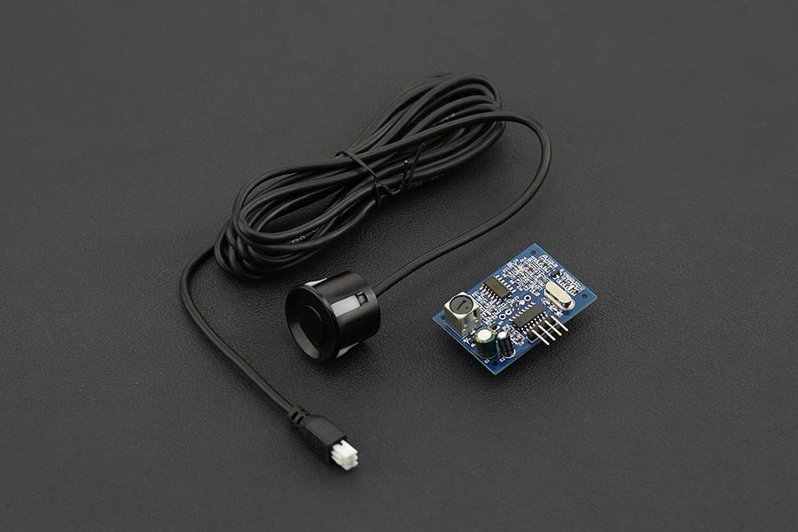
How do you deal with the problem that traditional non-waterproof ultrasonic distance sensor can not be used outside for a long time in rainy day. Now, don’t worry, this weather - proof ultrasonic sensor with separate probe can help you with this problem. With fully enclosed waterproof design, the module is suitable for outdoor applications in rainy days, such as car reverse ranging, security alarms, industrial inspection, etc.
Application: high precision long-distance ranging, obstacle avoidance, automatic control, object approach, existence detection, artificial intelligence, scientific research and experiment, traffic, security and industrial control
 NOTE:
NOTE:
- The module is not suggested to connect directly to electric, if connected electric, the GND terminal should be connected the module first, otherwise, it will affect the normal work of the module.
- When tested objects, the range of area is not less than 0.5 square meters and the plane requests as smooth as possible, otherwise, it will affect the results of measuring.
Specification
- Working voltage: DC3.3-5V
- Detection range: 30cm~500cm
- Accuracy: ±(1+S*0.5%)
- Measuring angle: 60°
- Static current: 8mA
- Working current: 40mA
- Working frequency: 40KHz
- Resolution: 3mm
- Temperature compensation: Yes
- Working temperature: -20 ~ 70°C
- PCB Size: 42 x29 x12 mm

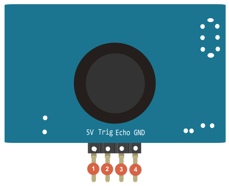
Board Overview

| LABEL | NAME | FUNCTION |
|---|---|---|
| 1 | 5V | Power Input + |
| 2 | Trig/RX | Signal control terminal / serial port input |
| 3 | Echo/TX | Signal receiving terminal/serial port output |
| 4 | GND | GND |
Tutorial
This tutorial will demonstrate how to use the Weather-proof Ultrasonic Sensor to measure distance.
Function Description
 NOTE: The inductor cannot be adjusted arbitrarily.
There are 6 operating modes as follows for customers to choose according to their own needs.

Mode 0: Mode=floating high level (PWM) pulse width output
(1) Pinout Definition
| Label | Name | Function |
|---|---|---|
| 1 | Trig | Trigger control pin |
| 2 | Echo | High level pulse width output |
(2) Fundamental Principles
- Adopt IO port TRIG to trigger ranging. Present a high level signal of at least 10us.
- The module automatically sends eight 40khz square waves and automatically detects whether a signal returns;
- When a signal returns, a high level is output through the IO port ECH0. The duration of the high level is the time from the transmission of the ultrasonic wave to the return. Test distance in normal temperature= (high level time * speed of sound (348M/S))/2.
- After the module is triggered for ranging, if the echo cannot be received (Reason: The ultrasonic wave exceeds the measured range or the probe doesn’t directly points at the measured object), the ECHO port will automatically become low after 40MS, marking the end of the measurement, regardless of success.
- The LED does not light up until there is a triggering signal to the TRIG pin. The frequency of light flashing is synchronized with the trigger cycle, indicating that the module receives the correct command and enters the working state at this time.
(3) Ultrasonic Timing diagram

The Timing diagram below shows that you only need to supply a short 10uS pulse to the trigger input to start the ranging, and then the module will send out an 8 cycle level at 40 kHz and raise its echo. Once an echo signal is detected, an echo signal is output. The pulse width of the echo signal is directly proportional to the measured distance. You can calculate the range through the time interval between sending trigger signal and receiving echo signal. Formula: uS / 57.5 = centimeters or uS / 148 =inch; or: the range = high level time * velocity (348M/S) / 2; we suggest to use over 50ms measurement cycle, in order to prevent effect caused by trigger signal to the echo signal.
Mode 1: Mode=47K (or directly short M1 bit) UART automatic output
The UART automatic output mode outputs the measured distance value (hexadecimal number) according to the UART communication format. This mode does not require an external trigger signal. The module can automatically measure every 100ms. The TX pin outputs the measured distance value after each measurement is completed.
(1) Pin Definition
| Label | Name | Function |
|---|---|---|
| 1 | TX | UART Output Pinout |
| 2 | RX | / |
(2) Communication Protocol
| UART | Baud Rate | Check Bit | Data Bit | Stop Bit |
|---|---|---|---|---|
| TTL | 9600bps | N | 8 | 1 |
(3) Format Description
| Frame | Description | Byte |
|---|---|---|
| Header | Fixed to 0xff | 1 byte |
| H_DATA | The upper 8 bits of the distance data | 1 byte |
| L_DATA | The lower 8 bits of the distance data | 1 byte |
| SUM | Data Checksum | 1 byte |
 NOTE: Checksum only reserves the low 8 bits of the accumulated value.
For Example:
- Product Response FF 07 A1 A7
- Where the check code SUM = A7 = (0x07 + 0xA1 + 0Xff) & 0x00ff
- 0x07 is the high bit data of the distance
- 0xA1 is the low bit data of the distance
- Distance value is 0x07A1
- Equal to 1953 when converted into decimal
- Unit: mm
 NOTE: The module outputs the nearest distance value of 21cm in the dead zone, and outputs 0 if the module does not measure the data or is out of range. After the LED is powered on and in the working mode, it will automatically flash with 100ms.
Mode 2: Mode=120K (or short M2 bit directly) UART controlled output
The UART controlled output method outputs the measured distance value (hexadecimal number) according to the UART communication format. In this method, the trigger command 0X55 signal needs to be added to the RX pin. The module measures once every time the command is received. The TX pin outputs the measured distance value. The command trigger cycle should be greater than 60ms.
(1) Pin Definition
| Label | Name | Function |
|---|---|---|
| 1 | TX | UART Output Pin |
| 2 | RX | UART Controlled RXD Pin(instruction 0X55) |
(2) Communication Protocol
| UART | Baud Rate | Check Bit | Data Bit | Stop Bit |
|---|---|---|---|---|
| TTL | 9600bps | N | 8 | 1 |
(3) Format Description
| Frame | Description | Byte |
|---|---|---|
| Header | Fixed to 0xff | 1 byte |
| H_DATA | The upper 8 bits of the distance data | 1 byte |
| L_DATA | The lower 8 bits of the distance data | 1 byte |
| SUM | Data Checksum | 1 byte |
 NOTE: Checksum only reserves the low 8 bits of the accumulated value.
For Example:
- Product Response FF 07 A1 A7
- Where the check code SUM = A7 = (0x07 + 0xA1 + 0Xff) & 0x00ff
- 0x07 is the high bit data of the distance
- 0xA1 is the low bit data of the distance
- Distance value is 0x07A1
- Equal to 1953 when converted into decimal
- Unit: mm
 NOTE: The module outputs the nearest distance value of 21cm in the dead zone, and outputs 0 if the module does not measure the data or is out of range. After the LED is powered on and in the working mode, the indicator will be on every time it is triggered, and the frequency is the same as the trigger cycle. The light will turn off every time it is triggered for two times.
Mode 3: Mode=470K (or directly short M3) switch output
Working description The module will set a threshold value when it leaves the factory, and the default value is 1.5 meters. The module performs distance measurement every 200ms. When the distance value of the detected target is less than the set threshold value, the Echo pin outputs a high level. When the current detected distance value is greater than the set threshold value, the Echo pin outputs a low level. In order to improve stability, the factory default is that if the distance value of the target is less than the set threshold value for two consecutive times, it is judged that the detected target distance is less than the set threshold value; the module Echo pin only outputs high and low level signals and has no driving ability. When applied, a transistor drive relay should be added. If there are special requirements to modify the threshold value or other settings, special instructions are required when purchasing.
(1) Pin definition
| Serial number | Label | Pin description |
|---|---|---|
| 2 | Trig | Switching low and high level output pin |
| 3 | Echo | Switching high level output pin |
Requirements
-
Hardware
- Arduino UNO x1
- Waterproof Ultrasonic Ranging Module x1
-
Software
- Arduino IDE V1.6.8. Click to Download Arduino IDE from Arduino
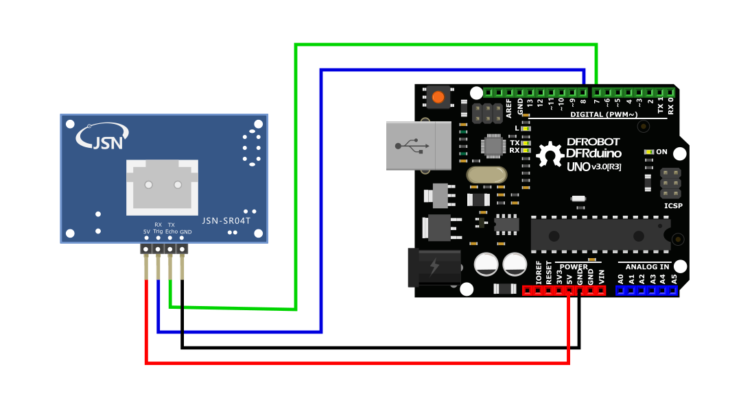
Connection Diagram

Sample Code
Mode 0
#define ECHOPIN 7// Pin to receive echo pulse
#define TRIGPIN 8// Pin to send trigger pulse
int distance;
void setup(){
  Serial.begin(9600);
  pinMode(ECHOPIN, INPUT);
  pinMode(TRIGPIN, OUTPUT);
  //digitalWrite(ECHOPIN, HIGH);

}
void loop(){
  digitalWrite(TRIGPIN, LOW); // Set the trigger pin to low for 2uS
  delayMicroseconds(2);
  digitalWrite(TRIGPIN, HIGH); // Send a 10uS high to trigger ranging
  delayMicroseconds(20);
  digitalWrite(TRIGPIN, LOW); // Send pin low again
  distance = pulseIn(ECHOPIN, HIGH)/58; // Read in times pulse
  //Serial.println(distance);
  Serial.print(distance);
  Serial.println("   cm");
  delay(50);// Wait 50mS before next ranging
}
Mode 1
/* ****************************************************
* @brief Water-proof Ultrasonic Sensor (ULS)

 * @copyright   [DFRobot](http://www.dfrobot.com), 2016
 * @copyright   GNU Lesser General Public License

* @author [huyujie]([email protected])
* @version  V1.0
* @date  2020-12-7

* GNU Lesser General Public License.
* All above must be included in any redistribution
* ****************************************************/

#include <SoftwareSerial.h>
unsigned char buffer_RTT[4] = {0};// Used to store data read from the serial port
int Distance = 0;//Used to store the read distance value
unsigned char CS;//Save checksum
SoftwareSerial mySerial(7, 8); // RX, TX
void setup() {
  Serial.begin(115200);
  mySerial.begin(9600);
}
void loop() {
  if(mySerial.available() > 0){
    delay(4);
    if(mySerial.read() == 0xff){    //Judge packet header
      buffer_RTT[0] = 0xff;
      for (int i=1; i<4; i++){
        buffer_RTT[i] = mySerial.read();    //Read data
      }
      CS = buffer_RTT[0] + buffer_RTT[1]+ buffer_RTT[2];  //Compute checksum
      if(buffer_RTT[3] == CS) {
        Distance = (buffer_RTT[1] << 8) + buffer_RTT[2];//Calculate distance
        Serial.print("Distance:");
        Serial.print(Distance);
        Serial.println("mm");
      }
    }
  }
}
Mode 2
/* ****************************************************
* @brief Water-proof Ultrasonic Sensor (ULS)

 * @copyright   [DFRobot](http://www.dfrobot.com), 2016
 * @copyright   GNU Lesser General Public License

* @author [huyujie]([email protected])
* @version  V1.0
* @date  2020-12-7

* GNU Lesser General Public License.
* All above must be included in any redistribution
* ****************************************************/

#include <SoftwareSerial.h>
unsigned char buffer_RTT[4] = {0};//  Used to store data read from the serial port
int Distance = 0;//Used to store the read distance value
uint8_t CS;//Save checksum
#define COM 0x55
SoftwareSerial mySerial(7, 8); // RX, TX
void setup() {
  Serial.begin(115200);
  mySerial.begin(9600);
}
void loop() {
  mySerial.write(COM , 1);
  delay(100);
  if(mySerial.available() > 0){
    delay(4);
    if(mySerial.read() == 0xff){    //Judge packet header
      buffer_RTT[0] = 0xff;
      for (int i=1; i<4; i++){
        buffer_RTT[i] = mySerial.read();    //Read data
      }
      CS = buffer_RTT[0] + buffer_RTT[1]+ buffer_RTT[2];  //Compute checksum
      if(buffer_RTT[3] == CS) {
        Distance = (buffer_RTT[1] << 8) + buffer_RTT[2];//Calculate distance
        Serial.print("Distance:");
        Serial.print(Distance);
        Serial.println("mm");
      }
    }
  }
}
Mode 3
    int ECHO = 7, Trig = 8;
    int i = 0, q = 0;
    void setup() {
      Serial.begin(9600);
      pinMode(ECHO, INPUT);
      pinMode(Trig, INPUT);
    }
    void loop() {
      i = digitalRead(ECHO);
      q = digitalRead(Trig);
      Serial.print("ECHO= ");
      Serial.print(i);
      Serial.print(" Trig= ");
      Serial.println(q);
      delay(1000);
    }
FAQ
For any questions, advice or cool ideas to share, please visit the DFRobot Forum.