Introduction
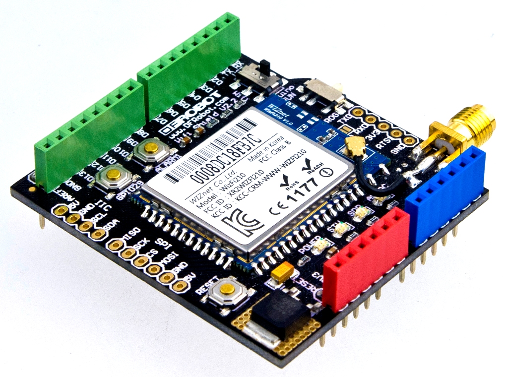
The shield uses WizFi210 which is a low power-consuming WIFI module which is applied with dynamic power management technology. When the WIFI module needs to be on but not work, it can be set to Standby mode a low power mode, and the module just needs to be woken up when it has to work. The WIFI wireless module is based on WizFi210. It provides the bridging from TTL serial port communication to IEEE802.11b/g/n wireless communication. So any device with TTL serial ports can easily be connected with this WIFI module and controlled and managed remotely through a wireless network. Different kinds of communication protocols and encryption algorithms are integrated with the module. The Arduino architecture enables you to easily integrate this module into any Arduino based project.
Specifications
- Wifi Chip: WizFi210
- Radio Protocol: IEEE 802.11b/g/n Compatible
- Supported Data Rates: 11, 5.5, 2, 1 Mbps (IEEE 802.11b)
- Modulation: DSSS and CCK
- RF Operating Frequency: 2.4 - 2.497 GHz
- Antenna Options: Chip antenna and U.FL connector for external antenna
- Networking Protocols: UDP, TCP/IP (IPv4), DHCP, ARP, DNS, HTTP/HTTPS Client and Server(*)
- Power Consumption(Typical): Standby = 34.0 µA Receive = 125.0 mA Transmit = 135.0 mA
- RF Output Power (Typical): 8dBm ± 1dBm
- Security Protocols: WEP, WPA/WPA2–PSK, Enterprise, EAP-FAST, EAP-TLS, EAP-TTLS, PEAP
- I/O Interface: UART, SPI(*), I2C(*), WAKE, ALARM, GPIOs
- Working Voltage: 5V
- Chip working voltage: 3.3V
- Dimensions(except Antenna): 59 x 54 mm
NOTE: Power supply and I/O working voltage is 5V. Although the chip WizFi210 working voltage is 3.3V, we have made it compatible with 5V instead to get it work with most Arduino card. You can check its schmatic for more details. |
Pinout Diagram
Get Started with Wifi sheild
In this section, we will use the Wifi shield to create a Web server as an sample application.Let's follow the steps below to make it work!
Tools need
Here's all the hardware needed.
- Arduino UNO processor x1
- WIFI shield for Arduino v2.2 x1
- WIFI Antenna
- A to B USB Cable x1
- Router x1
Hardware setting
- Program a simple led blinking sample code for your Arduino UNO first to avoid the serial communication conflict between USB port to the WIFI shield.
- Stack the WIFI shield to the Arduino Uno and connect the antenna to the WIFI shield
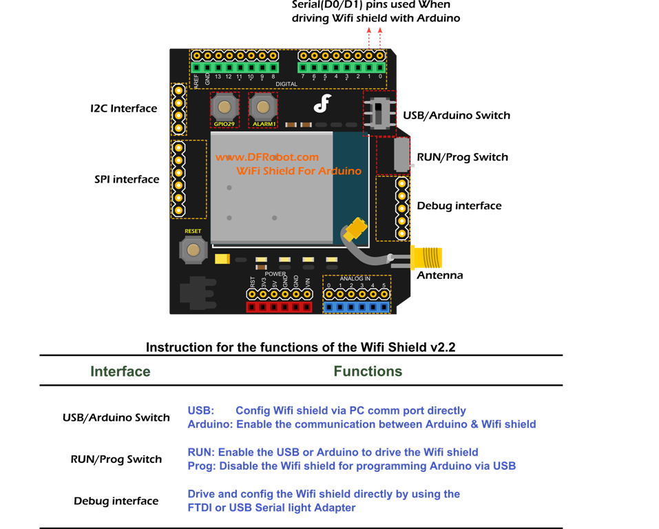
- Set the "USB/Arduino" Switch to the USB side to enable PC com port to send AT command to WIFI shield directly
- Set the "Run/Prog" Switch to RUN side
- Plugin the A to B USB to the Arduino microcontroller. The "POWER" LED turns on at the same time.
Config the WIFI shield setting via USB com port
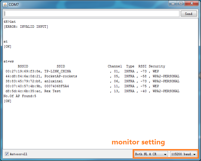
We need a serial monitor for configuring the WIFI shield setting in this part. There're lots of good tools like putty, CoolTerm and Arduino serial monitor. In this case, we choose the Serial monitor included in Arduino IDE. Please set the baud rate to 115200 bps and Both NL&CR.
- Open the com port of your Arduino UNO. Enter "at" to test the communication between WIFI shield and the USB port.
- Enter "AT+WS" command to scan the network and get the list of found networks like the picture(Fig1) shown.
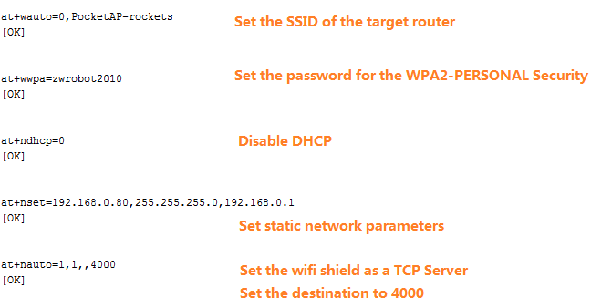
- Setting the WIFI shield according to the router information. List the sample command below(Fig2).
- Note
- The SSID,password and the security setting depends on the your router setting. So please check the router first.Otherwise,if the setting isn't correct,the wifi shield can't connect the router properly.
- The gateway of my router is "192.168.0.1". But usually it's "192.168.1.1".So please check the setting of your network also. And set the right IP address for your WIFI shield.
- Note
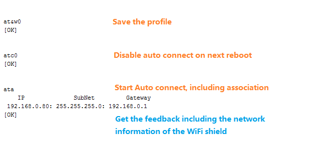
- Then save the setting(Fig3). Otherwise all the setting above will be cleared after resetting.
- After getting the feedback from WiFi shield correctly, we finish the setting for the WiFi shield and create a TCP server in the local network.And the indicator LEDs(marked "STW" and "ASSOC")will turn on to indicate the connection with the router.
- Then let's start to create a client and send message to our WiFi shield. _≧▽≦)/
Connect to the TCP server from WiFi shield
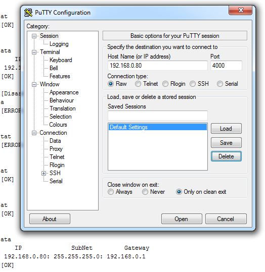
In this section, I choose putty to work as an TCP client and send commands to the WIFI shield.
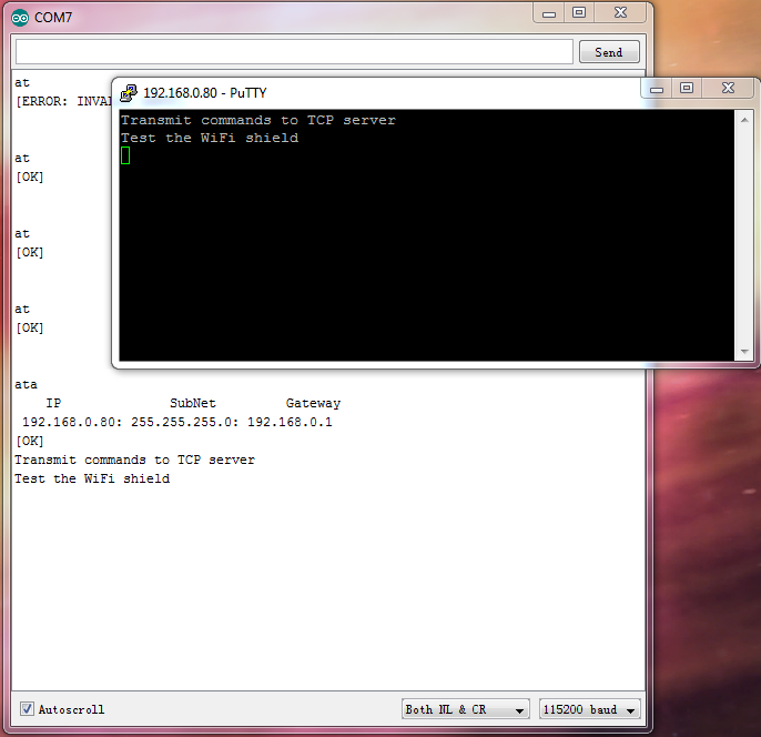
- Config the Host Name and Port.Set the connection type to Raw and Press open! Then you will connect to the server created by WIFI shield.
- Now you could send commands via the TCP client simulated by putty to the WIFI shield. And putty will receive the strings sent from the Serial monitor also.
Documents
- Schematic
- User manual for checking more commands for configuring the WIFI shield
- Configuration Software
