Introduction
FireBeetle 2 ESP32-S3(N4) is a main control board designed based on the Espressif ESP32-S3-WROOM-1-N4 module. It features a 32-bit dual-core processor with a clock frequency of 240MHz and a built-in 4M FLASH memory. It supports dual-mode communication of WIFI and Bluetooth 5.0. Additionally, it also supports Bluetooth Mesh protocol and Espressif Wi-Fi Mesh, providing higher communication stability, larger coverage area, longer transmission distance, and more device interconnectivity.
The ESP32-S3 chip is equipped with AI acceleration capability, enabling it to perform neural network calculations and signal processing tasks. This allows it to meet the performance requirements of low-computational AI edge computing tasks such as simple voice command recognition, text recognition, and sensor data recognition. Therefore, it is not only suitable for IoT scenarios but also plays an important role in simple, low-computational AIoT projects.
In terms of product features, FireBeetle 2 ESP32-S3(N4) has the following characteristics:
Rich peripheral interfaces
It includes 18 analog pins, 26 digital pins, 3 UART interfaces, 3 SPI interfaces, 3 I2C interfaces, 2 I2S interfaces, 10 infrared transceivers, and 10 DMA controller channels. Additionally, it provides an onboard GDI display interface to meet various hardware connection requirements.
Dual power supply modes
It supports both USB and external lithium battery power supply and can automatically switch between power sources in dual power supply mode. Furthermore, it supports both USB and external DC charging modes and allows hardware to control power on/off settings.
Support for multiple programming methods
Including Arduino IDE, idf, MicroPython, C language, and Python, catering to the programming preferences of different developers.
Compact design, convenient for embedding
With dimensions of only 25.4mm × 60mm, it has onboard WIFI and Bluetooth antennas and adopts a stamp hole design, making it easy to embed or integrate into PCB prototypes.
Wide range of application scenarios
It is suitable for various scenarios such as home automation renovation, IoT device prototyping, IoT remote monitoring, and remote robot control. Additionally, it is also applicable to low-computational AI edge computing, voice command recognition, text recognition, and sensor data recognition applications.
Furthermore, this product is one of the low-power IoT development boards in the FireBeetle series. If it does not meet your requirements, you can refer to the FireBeetle Series Selection Guide to choose a more suitable model.
If there is a programming failure, please connect the USB, hold down the BOOT button, click the RST button, and then release the BOOT button to put the development board into download mode.
Features
- Equipped with ESP32-S3-WROOM-1-N4 dual-core module, supporting AI acceleration.
- Clock frequency up to 240MHz, with built-in 512KB SRAM and 4M Flash.
- Supports dual-mode communication of Wi-Fi and Bluetooth 5 (LE).
- Integrated power management, supporting lithium battery charging and hardware power on/off.
- Onboard independent GDI display interface, enabling quick connection to display screens.
- Supports various programming methods such as Arduino IDE, ESP-IDF, and MicroPython.
- Compact design with small size, suitable for IoT and AIoT projects with limited space and embedded systems.
Specification
- Basic Parameters
- Input Voltage
- USB-C interface: 5V DC
- PH2.0 interface: 3.7V Li-ion
- VCC pin: 5V DC
- Interface: FireBeetle V2 series compatible
- Module Size: 25.4mm × 60mm
- Weight: 23.4g
- Input Voltage
- Hardware Information
- Processor: Xtensa® dual-core 32-bit LX7 microprocessor
- Clock Frequency: 240 MHz
- SRAM: 512KB
- ROM: 384KB
- Flash: 4MB
- RTC SRAM: 16KB
- USB: USB 2.0 OTG full-speed interface
- WIFI
- WIFI Protocol: IEEE 802.11b/g/n
- WIFI Bandwidth: 2.4 GHz band supports 20 MHz and 40 MHz bandwidth
- WIFI Modes: Station mode, SoftAP mode, SoftAP+Station mode, and mixed mode
- WIFI Frequency: 2.4GHz
- Frame Aggregation: TX/RX A-MPDU, TX/RX A-MSDU
- Bluetooth
- Bluetooth Protocol: Bluetooth 5, Bluetooth mesh
- Bluetooth Frequency: 125 Kbps, 500 Kbps, 1 Mbps, 2 Mbps
- Interface Pins
- Digital I/O x26
- SPI x2
- UART x3
- I2C x2
- I2S x2
- LED PWM controller with 8 channels
- Infrared transceiver: 5 transmission channels, 5 reception channels
- 2 × 12-bit SAR ADC, 20 channels
- DMA controller, 5 reception channels, and 5 transmission channels
Board Overview

- Type-C: Type-C USB port
- 21/D13: onboard LED pin
- 47/D14: IO/Power Control Pin. By default, Long press 6s to power off, press 2s to power on
- ESP32-S3: ESP32-S3-WROOM-1-N16R8 or ESP32-S3-WROOM-1U-N16R8 module
- RST: Reset button
- BOOT: Boot button
- AXP313A: Power management chip
- ETA6003: ETA6003 Li-ion Battery Charging Managment chip
- BAT: Li-ion battery port
- Charge: Charging indicator
- Off: not plugged in power supply or fully charged
- On: charging
- Blinking: battery not connected
- GDI: GDI display interface
Pin Diagram

Pin Definition
- GPIO: general input/output
- Analog: analog input pin
- ADC: analog to digital conversion
- TOUCH: touch pin
- SPI: SPI interface
- I2C: I2C interface
- UART: UART interface
- USB: USB interface
- JTAG: debug interface
- 3V3: 3.3V stable output
- VCC: power input/output
- Input:5V DC input for powering FireBeetle(Cannot charge Li-ion battery)
- Output: output USB voltage when powered by 5V-USB;output battery voltage when powered by 3.7V Li-ion battery
- GND: common ground pin
GPIO Configuration

GDI Display Interface
This interface is a DFRbot dedicated GDI display interface for connecting a screen using a 18pin-FPC wire.
The pin list for using GDI camera interface is shown below:
| FPC PINS | Beetle ESP32 S3 Pins | Description |
|---|---|---|
| VCC | 3V3 | 3.3V |
| LCD_BL | 21/D13 | Backlight |
| GND | GND | GND |
| SCLK | 17/SCK | SPI clock |
| MOSI | 15/MOSI | Host output, slave input |
| MISO | 16/MISO | Host input, slave output |
| LCD_DC | 3/D2 | Data/command |
| LCD_RST | 38/D3 | Reset |
| LCD_CS | 18/D6 | TFT Chip Select |
| SD_CS | 9/D7 | SD card chip select |
| FCS | 7/D6 | Font library chip select |
| TCS | 12/D12 | Touch chip select |
| SCL | 2/SCL | I2C clock |
| SDA | 1/SDA | I2C data |
| INT | 13/D11 | INT |
| BUSY | 4/D10 | Tearproof pins |
| X1 | NC | custom pin 1 |
| X2 | NC | custom pin 2 |
When using FPC to connect the screen, please configure the corresponding pin numbers according to the GDL demo. Normally, only three pins need to be configured on different main controllers.
Displays that support GDI:
- 1.54" 240x240 IPS wide viewing angle TFT display
- 1.8" 128x160 IPS TFT LCD Display
- 2.0" 320x240 IPS wide viewing angle TFT display
- 2.8" 320x240 IPS TFT resistive touch display
- 3.5" 480x320 IPS TFT capacitive touch display
- 1.51" OLED Transparent Display with Converter
Dimensional Diagram
- Pin pitch: 2.54mm
- Mounting hole spacing: 22mm and 56.6mm
- Mounting hole size: 2mm
- Board dimensions: 25.4.00mm × 60.00mm
- Board thickness: 1.6mm
Tutorial - First Time Use
Arduino IDE Configuration
Please pay attention to the followings when using FireBeetle 2 ESP32-S3(N4) for the first time.
- Add the json link in the IDE
- Download the core of the MCU
- Select the development board and serial port
- Open the sample code and burn it into the board
- Get to know the serial monitor
Arduino IDE compiler environment config
-
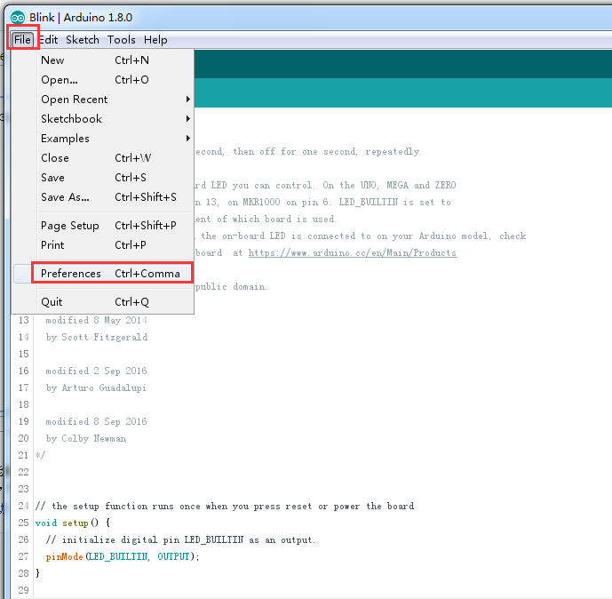
Open Arduino IDE and click File->Preferences, as shown below.
-
In the newly opened interface, click the button in the red circle as shown below

-
Copy the following link into the new pop-up dialog box: https://raw.githubusercontent.com/espressif/arduino-esp32/gh-pages/package_esp32_index.json
Note: If you have installed another environment before, you can press Enter key at the beginning or end of the previous link and paste the link at a new line.

-
Click OK.
-
Update the board. Open Tools->Board:->Boards Manager... as shown below:

-
Boards Manager will automatically update the boards as shown below:

-
After the update is completed, you can enter "esp32" in the search bar above. When you see the following situation, select "esp32" and click on "Install" (it is recommended to install the latest version):

-
Please wait for the progress bar below to finish:

-
Once the installation is complete, the list will display the installed ESP32 board, as shown in the following image:

-
Click on Tools->Board: and select DFRobot FireBeetle 2 ESP32-S3.

-
Before you begin, you also need to configure the following settings:
(When you select "Disabled", the serial port will be RX(44) and TX(43). If you want to print on the Arduino monitor via USB, you need to select "Enable".)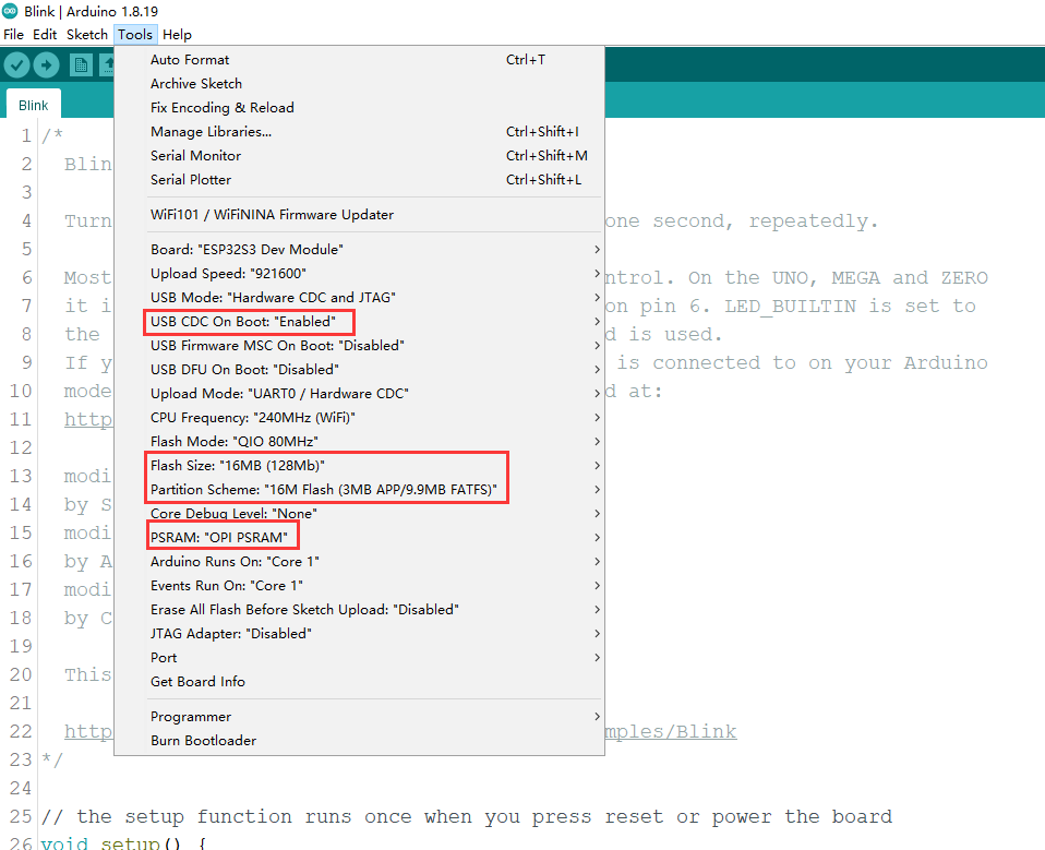
-
Click on Port and select the corresponding serial port.

LED Blink
The onboard LED is connected to pin 21 by default.
Code
int led = 21;
void setup() {
  pinMode(led, OUTPUT);
}

void loop() {
  digitalWrite(led, HIGH);
  delay(1000);
  digitalWrite(led, LOW);
  delay(1000);
}
- Copy and paste the above code into the code editor.
- Click on the arrow to compile and upload the program to the development board.
Upload Successful

- The upload is successful as shown in the image.
- You will see the onboard LED start blinking.
- Still having trouble uploading? Click here
Basic Tutorials
The basic tutorials include tutorials on PWM, interrupts, serial communication, servos, and SD card.
Advanced Tutorials
Note: FireBeetle 2 ESP32-S3(N4) does not support camera functionality, so you don't need to refer to the camera-related content in the tutorials.
The advanced tutorials include tutorials on screen display, Bluetooth, Wi-Fi, ESP-NOW, project examples, one-click configuration, and camera.
Tutorial for MicroPython
Build Environment for MicroPython
To run microPython on the FireBeetle 2 ESP32-S3(N4), you need to burn the firmware into FireBeetle 2 ESP32-S3(N4) first.
-
Click to download microPython firmware.
- MicroPython official firmware (Note: Please select Support for Octal-SPIRAM version)
- DFRobot MicroPython firmware-with camera driver
-
Run flash_download_tool_3.9.3.exe
-
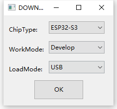
Select the ESP32-S3 main controller, than Press Boot, press RST and release both, then try burning again.
-
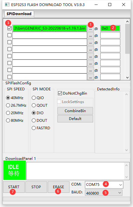
Select the downloaded firmware, clear the flash and then burn the firmware.
MicroPython Interpreter
-
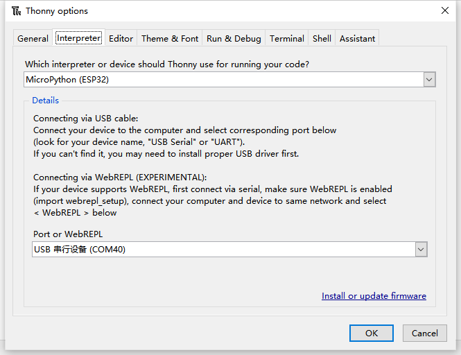
Open the software and set up the interpreter (Run->Configure interpreter...)
-
Copy and paste the code into the code box, save the file to the MicroPython device and name it main.py
import time
from machine import Pin

led=Pin(21,Pin.OUT)

while True:

 led.value(1)
 time.sleep(1)
 led.value(0)
 time.sleep(1)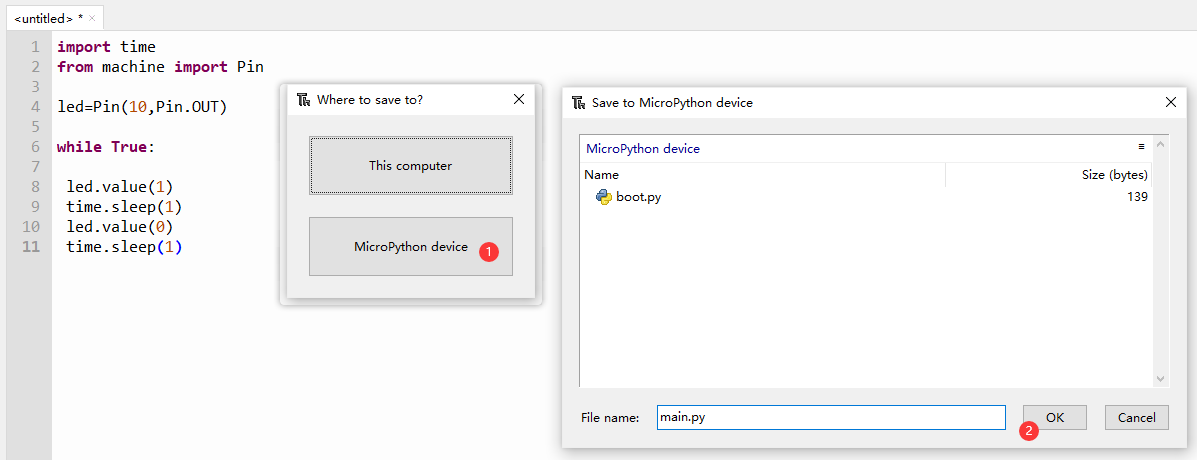
-
Reboot the FireBeetle 2 ESP32-S3, and you can see the L LED flashing.
MicroPython Tutorial
FAQ
1. What will cause burning error?
-
There is no delay or too short delay in Loop.

-
The USB cannot be recognized by the PC as some functions are incorrectlly called.
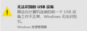
How to solve
- Press Boot, press RST and release both, then try burning again.
2. Data cannot be printed on serial port
- Check if the USB CDC is enabled
- Check print information using other serial debugger.
2. Drive multiple servos in the same time
- If you can't drive multiple servos at the same time using the servo library in Basic Tutorial. Please use the ESP32-AnalogWrite library.
For any questions, advice or cool ideas to share, please visit the DFRobot Forum.
