Introduction
The DFRobot Fermion I2C address shifter is a module that changes the address of I2C sensors. By hooking up this module between dev board and the sensor, the sensor will be recognised by the dev board with the new address. The module is plug-and-play, compact in size and easy to integrate into any I2C cascade system. Four new addresses can be obtained by adjusting the on-board dip switches, and at least 20 new addresses can be obtained additionally by soldering on-board resistors.
I2C communication is favoured by many developers in the open source hardware ecosystem because of its simplicity of connectivity and support for multiple dev board and sensors. Theoretically, it is possible to drive 127 devices with different addresses on one I2C channel at the same time. However, in practice, the problem of two sensors with the same address is bound to be encountered.
The solution in the past was to switch sensor ports through I2C multiplexer, but this would require developers to have some experience in developing I2C devices to avoid the possible timing effects of multiplexer. And frequent port switching in the main code would also greatly reduce code readability.
The DFRobot I2C address shifter provides a hardware solution, where the address conversion is done entirely inside the shifter, and the I2C physical address can be changed directly with a simple wire connection, without the need for complex port switching in the code, and without triggering any I2C timing bugs.
Although the I2C address shifter is powerful and easy-to-use, user need to pay attention to the following two things before using it:
- The address shifter does not support clock extension, so it is not suitable for special I2C sensor like the BNO055.
- Before using the address shifter, user need to understand how to change the sensor's I2C address in the code.
Product Characteristics
- Hardware solution, no additional software libraries required
- On-board dip switch to change the I2C sensor into four different addresses
- Compact size and stamp hole design for easy bulk integration
Specification
- Working voltage:2.25V-5.5V
- Working temperature:0~70℃
- Working current:2mA @3.3V
- Dimension:19*19mm
- R2 pad package: 0805
Pinout


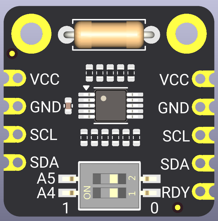
| Controller Side | Description |
|---|---|
| VCC | DC2.25V-5.5V input |
| GND | Ground |
| SCL | I2C Clock(To I2C controller) |
| SDA | I2C Data(To I2C controller) |
| RDY | Outputs a high level when I2C sensor address translation is complete I2C sensor address translation not completed output low level |
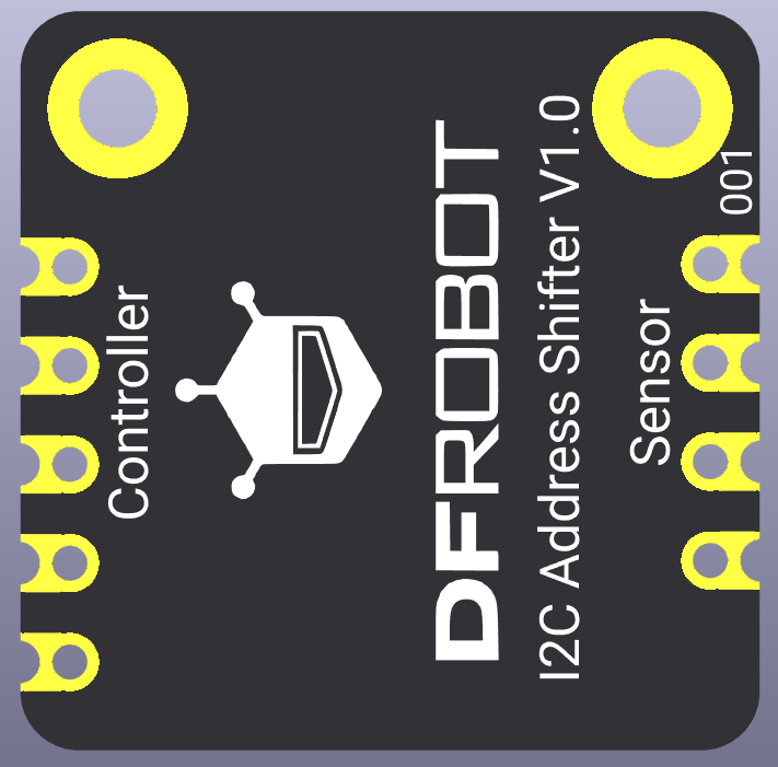
| Sensor Side | Description |
|---|---|
| VCC | DC2.25-5.5V Output |
| GND | Ground |
| SCL | I2C Clock(To I2C sensor) |
| SDA | I2C Data(To I2C sensor) |
| Dip Switch | Description |
|---|---|
| A5 | Controls whether the fifth bit of the I2C address is inverted (1 is invert, 0 is not invert) |
| A4 | Controls whether the fourth bit of the I2C address is inverted (1 is invert, 0 is not invert) |
I2C Address Calculate
The I2C address has 7bit, we define A6 as the highest bit and A0 as the lowest bit.
The address shifter always inverts A6 bit by default (from 0 to 1 and from 1 to 0). You can also control whether bits A5 or A4 are inverted or not by using the on-board dip switches.
Assuming that the default address of the sensor is 0x69, which is 0b1101001 in binary, after the sensor is connect to the address shifter:
| Original Address(bin) | A5 dip switch | A4 dip switch | New Address(bin) | New Address(hex) |
|---|---|---|---|---|
| 1101001 | 0 | 0 | 0101001 | 0x29 |
| 1101001 | 1 | 0 | 0001001 | 0x09 |
| 1101001 | 0 | 1 | 0111001 | 0x39 |
| 1101001 | 1 | 1 | 0011001 | 0x19 |
In the meantime, you need to be aware of the following.
- Fermion: The I2C address shifter needs to be powered up again after adjusting the on-board dip switch to set the new address.
- If you are using a Windows computer, you can use the programmer function of the calculator that came with your computer to do hexadecimal (HEX) to binary (BIN) conversions
- In the above address description: 0b is the prefix of a binary number, which means the data that follows is in binary; 0x is the prefix of a hexadecimal number, which means the data that follows is in hexadecimal.
Tutorial
Preparation
Hardware
- DFRduino UNO+IO expantion board (SKU:DFR0216-2) ×1
- Gravity: BMI160 6-axis Inertial Motion Sensor(SKU:SEN0250)×2
- Fermion I2C Address shifter(SKU:DFR1185)×1
- Jumper wire(F/F)
Software
- Arduino IDE: Download Arduino IDE
- Library:DFRobot BMI160 Github
- Arduino IDE V1.8.19 (or below) installation library files:How to install library
- Arduino IDE V2.0.0 (or above) can be installed by searching for the ‘DFRobot_BMI160’ library in the library manager.
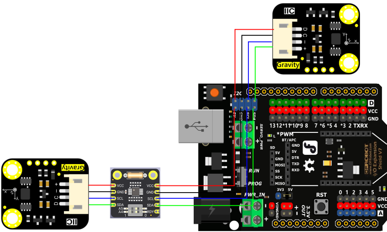
Wiring Diagram

Sample code
-
Check the on-board dip switch is set to A5=0,A4=0, connect according to the wiring diagram above.
-
Upload the following code
  /*
 @file accelGyroscope.ino
 @brief Obtain accelerometer data in both BMIs.
 @copyright Copyright (c) 2010 DFRobot Co.Ltd (http://www.dfrobot.com)
 @license The MIT License (MIT)
 @author [thdyyl]([email protected])
 @version V0.1
 @date 2024-08-05
*/
#include "DFRobot_BMI160.h"
DFRobot_BMI160 bmi160_1, bmi160_2;
const int8_t i2c_addr_1 = 0x69, i2c_addr_2 = 0x29;

void setup(){
  Serial.begin(115200);
  delay(100);

  //init the default bmi160
  if(bmi160_1.softReset() != BMI160_OK){
    Serial.println("bmi160_1 reset false");
    while(1);
  }

  if(bmi160_2.softReset() != BMI160_OK){
    Serial.println("bmi160_2 reset false");
    while(1);
  }

  //set and init the bmi160 i2c address
  if(bmi160_1.I2cInit(i2c_addr_1) != BMI160_OK){
    Serial.println("bmi160_1 init false");
    while(1);
  }

  if(bmi160_2.I2cInit(i2c_addr_2) != BMI160_OK){
    Serial.println("bmi160_2 init false");
    while(1);
  }
}

void showAccelGyroData(DFRobot_BMI160 bmi160){
  int i = 0;
  int rslt;
  int16_t accelGyro[6] = {0};

  //get both accel and gyro data from bmi160
  //parameter accelGyro is the pointer to store the data
  rslt = bmi160.getAccelGyroData(accelGyro);

  if(rslt == 0){
    for(i = 0; i < 6; ++i){
      if(i < 3){
        //the first three are gyro datas
        Serial.print(accelGyro[i] * 3.14 / 180);
        Serial.print("\t");
      }else{
        //the following three data accel datas
        Serial.print(accelGyro[i] / 16384.0);
        Serial.print("\t");
      }
    }
    Serial.println();
  }
  else{
    Serial.println("err");
  }
}

void loop(){
  Serial.print("bmi160_1:\t");
  showAccelGyroData(bmi160_1);
  Serial.print("bmi160_2:\t");
  showAccelGyroData(bmi160_2);
  Serial.println();
  delay(500);
}
Result
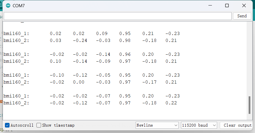
Serial monitor outputs the data of two Gravity: BMI160 6-axis Inertial Motion Sensor。

Advance tutorial
Fermion: The I2C address shifter can be switched via on-board dip switch to set the sensor to four different addresses.
If this is not enough for your needs. We have reserved a 0805 resistor pad (R2) on the module, you can refer to the schematic and Page 9 of the datasheet at the bottom of this wiki,solder the resistor to control whether the remaining I2C address bits are inverted.
This pad is connected to the XORL pin, which controls whether the lower four bits of the I2C address are inverted or not. We fixed RLB (R1 in our schematic) to 100kΩ, and you can calculate the resistance value of RLT (R2 in our schematic) and solder it yourself.
Here is how we determine an R2:
-
Firstly, from the datasheet, the module determines whether a bit of the I2C address is inverted or not by the voltage of the XORH or XORL pin, i.e. the ratio of VXORH or VORL relative to VCC. In table 2 and table 3 of the datasheet, a 1 under bit means inverted and a 0 means no inverted.

-
Assuming that the module supply VCC is now 5V, we want to set A3-A0 to a 1 0 0 0 mode, i.e. A3 inverts and A2~A0 do not. That means the VOXRL/VCC ratio should be 0.53125 ±0.015
-
To help you quickly calculate the resistance, the DFRobot R&D team has summarised a general formula:
[VCC/(R1+R2)]R1=VXORL
Where VCC has been specified as 5V in the previous assumptions and R1 is known to be 100kΩ, the target VXORL should be 0.53125*5V = 2.65625V
After substituting all the known parameters into the general formula above, it is possible to arrive at R2 ≈ 88.23529kΩ -
Given that the calculated R2 is not a common resistance value, we need to match it to the closest common resistance value and verify this common resistance value by substituting it back into the common formula.
In this case, the closest common resistance value to 88.23529kΩ is 86.6kΩ, which when substituted into the calculation gives VXORL ≈ 2.67953V, or VXORL/VCC ≈ 0.53906. This ratio falls in the range of 0.53125 ± 0.015, so we can use 86.6kΩ as the resistance value for R2.
To help save you the tedious calculations, we've helped you list a few R2 resistance values that we've verified:
| R2 | A3 | A2 | A1 | A0 |
|---|---|---|---|---|
| 91kΩ/86.6kΩ | 1 | 0 | 0 | 0 |
| 68kΩ | 1 | 0 | 0 | 1 |
| 51kΩ | 1 | 0 | 1 | 0 |
| 39kΩ | 1 | 0 | 1 | 1 |
| 27kΩ | 1 | 1 | 0 | 0 |
If you are unsure of the new address after soldering the resistor, we recommend using an Arduino or ESP32 and uploading the I2C scanner to find our the new address.
FAQ
Q1: Why did the sensor address not change after adjusting the on-board dip switch.
A1: Fermion: I2C Address Shifter needs to be power off and on after adjusting the dip switch for the new address.
Q2: Why do I need to solder resistor to adjust the lower four bits of the I2C address, instead of also designing more dip switch to adjustment other bit?
A2:Dip Switch schange the address by connecting a large number of resistors in parallel or not. If the lower four bits are also use the dip switch, this will greatly increase the number of resistors on board.This makes the size of this module very large.
Q3:How to quickly confirm the new I2C slave address after changing toggles or soldering resistors
A3:You can connect the sensor to an Arduino or ESP32 via an address converter and upload the I2C Scanner code below. The serial monitor will output the new I2C address.
/**
   @file i2cScanner.ino
   @brief The i2c_scanner see if a device did acknowledge to the address.
   @copyright Copyright (c) 2010 DFRobot Co.Ltd (http://www.dfrobot.com)
   @license The MIT License (MIT)
   @author [thdyyl]([email protected])
   @version V0.1
   @date 2024-08-05
*/
#include <Wire.h>

void setup(){
  Wire.begin();
  Serial.begin(115200);
  Serial.println();
  Serial.println("I2C Scanner");
}

void loop(){
  uint8_t error, address;
  int numDevices;
  Serial.println("Scanning...");
  numDevices = 0;
  for (address = 1; address < 127; address++ ){
    // The i2c_scanner uses the return value of the
    // Write.endTransmisstion to see if a device
    // did acknowledge to the address.
    Wire.beginTransmission(address);
    error = Wire.endTransmission();
    if (error == 0){
      Serial.print("I2C device found at address 0x");
      if (address < 16)
        Serial.print("0");
      Serial.print(address, HEX);
      Serial.println(" !");
      numDevices++;
    }else if (error == 4){
      Serial.print("Unknow error at address 0x");
      if (address < 16)
        Serial.print("0");
      Serial.println(address, HEX);
    }
  }
  if (numDevices == 0)
    Serial.println("No I2C devices found\n");
  else
    Serial.println("done\n");
  delay(2000); // wait 2 seconds for next scan
}
More
WIKI Modification History
| Doc version | Modification Time | Editor | Comment |
|---|---|---|---|
| V1.0 | 2024.11.25 | YeezB | First Release |
| V1.1 | 2025.2.25 | YeezB | Add STEP model |
Product
| Product version | Modification Time | Editor | Comment |
|---|---|---|---|
| V1.0 | 2024.11.25 | YeezB | First Release |

